


チコーエアーテック株式会社
Copyright CHIKO AIRTEC CO., LTD. 2009
6
3
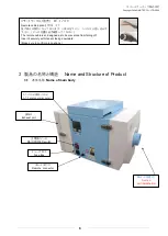
製品の名称と構造
Name and Structure of Product
3.1
本体名称
Name of main body
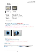
排気口
Exhaust port
AT パネル(操作パネル)
AT-Panel(operation panel)
主電源スイッチ
MAIN POWER switch
ヒューズ BOX
Fuse Box
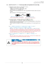
リモートコネクタ
Remote
connector
リモートケーブル(別売) MT-173-8
Remote cable(option)
(3m) ×1
抜け防止の設計となっております。くぼみを下にし、しっかりと差し込んで
下さい。
(ピンの位置を必ず確認してください)
The remote cable is so designed as to be prevented from falling off.
Insert it securely with its dent facing downward.
(Make sure to confirm pin positions.)
吸込口(脱着式)
Suction
port(detachable)


