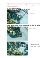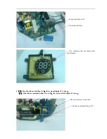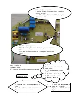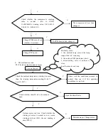
The indoor PCB fault
,
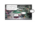
check whether the communication circuit on
the indoor PCB has been damaged, check especially some
important electric parts ,such as the optical coupler
、
voltage
stabilizing diode
、
resistor
、
PTC ,and so on ;(Fig. 10)
The faulty cause
:
1, hardware fault for PFC
2, the communication wire is broken off or connected
wrongly
;
、
3
、
the power ground wire isn’t connected reliably
;
、
4
、
the indoor PCB’s hardware has been damaged
;
5, the outdoor PCB’s hardware has been damaged
7
、
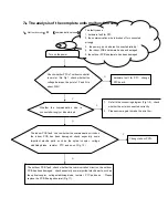
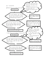
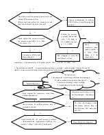
The analysis of the complete units malfunction code
1
、
Malfunction code
:
F1
(
communications issue
)
Y
Turn on the power
1
、
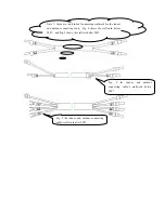
Refer to the connecting diagram (Fig 1~9)
,
check
whether the wire is connected correctly.
2
、
Please screw again to make the wire firm.
Whether the communication wire is
connected wrongly or disentwined.
N
Y
Change indoor PCB.
N
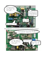
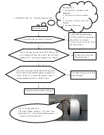
The outdoor PCB fault , check whether the communication circuit on the outdoor
PCB has been damaged
,
check especially some important electric parts ,such as
the optical coupler
、
voltage stabilizing diode
、
resistor
、
PTC and so on
;
Please
replace the PCB if being abnormal (Fig. 11)
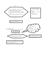
Check whether PFC of outdoor controller
is normal.
(
Re. Fig 1
,
check whether the
voltage between the point of P and N is
about 300V
)
hardware fault for PFC
,
change
PFC board.
N
Y
Summary of Contents for CS-25V1A-H1; CS-35V1A-E2; CS-50V9A-S; CS-70V9A-T
Page 1: ...DC Inverter Split Air Condition Unit SERVICE MANUAL ...
Page 3: ...3 1 Air conditioning unit parameters ...
Page 6: ...6 ...
Page 8: ...8 The curve diagram of the compressor condensing pressure ...
Page 12: ...12 Capacity Correction Factor Due to Tubing Length One Way Cooling Heating ...
Page 13: ...13 Pressure Curve Suction Pressure Curve Discharge Pressure Curve ...
Page 15: ...15 4 Indoor and outdoor units size 4 1 outdoor Unit CS 25V1A H1 4 2 outdoor Unit CS 35V1A E2 ...
Page 16: ...16 4 3 outdoor Unit CS 50V9A S 4 4 outdoor Unit CS 70V9A T ...
Page 19: ...19 ...
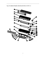
Page 20: ...20 5 2 The explosion diagram and spare parts list for CS 25V1A M81A ON OFF ...
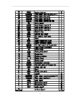
Page 21: ...21 ...
Page 22: ...22 5 3 The explosion diagram and spare parts list for CS 35V1A E2 ...
Page 23: ...23 ...
Page 24: ...24 5 4 The explosion diagram and spare parts list for CS 35V1A P81A ON 0FF F ...
Page 25: ...25 ...
Page 26: ...26 5 5 The explosion diagram and spare parts list for CS 50V9A S ...
Page 27: ...27 ...
Page 28: ...28 5 6 The explosion diagram and spare parts list for CS 50V9A S81A ON 0FF F ...
Page 29: ...29 ...
Page 30: ...30 5 7 The explosion diagram and spare parts list for CS 70V9A T ...
Page 31: ...31 ...
Page 32: ...32 5 8 The explosion diagram and spare parts list for CS 50V9A S ...
Page 33: ...33 ...

