background image

Installation Instructions

PWC-2000

9

4.

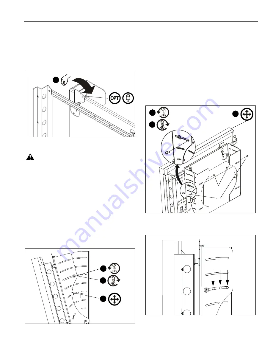
Rotate Q-Latch to the CLOSED position (See Figure 9).

NOTE:

If Q-Latch does not fully close, ensure mounting

buttons are fully seated in the button openings.

NOTE:

OPTIONAL: A hole is provided in both the Q-Latch and
the front plate to accommodate the insertion of a
padlock or similar locking device.

Figure 9

WARNING:

Make sure the latch securing the display is fully

closed at all times except when removing or installing the
display. The latch must be fully closed when installing or
removing cables from the display.

5.

Attach all cables to display and CPU.

TILT ADJUSTMENT

If desired, the display may be tilted to any position between 0°
and 15°.

1.

Using key (F),

slightly

 loosen upper front plate attach

screws (See Figure 10). Do NOT remove screws!

2.

Tilt display to desired angle.

3.

Tighten upper attach screws.

Figure 10

TILT LOCK

If desired, the display may be locked at 0°, 5°, or 10°.

NOTE:

A positive stop exists at 15° without the use of tilt lock

screws.

1.

Using key (F),

slightly

 loosen the upper front plate attach

screws (See Figure 10). Do NOT remove screws.

2.

Using key (F), loosely install screw (B) through slot in front
plate and applicable open tilt lock hole in side plate, into nut
(D) (See Figure 11)(See Figure 12).  Repeat for opposite
side.

3.

Tilt display until lock is reached.

4.

Tighten all four screws: upper front plate attach, and (B).

Figure 11

Figure 12

4

1

2

3

x2

x2

2

3

4

(B, D) x2

(B, D) x2

D

B

10°

Summary of Contents for PWC-2000

Page 1: ...ção Istruzioni di installazione Installatie instructies Instructions d installation Large Flat Panel Tilt Wall Mount with Integrated CPU Enclosure Spanish Product Description German Product Description Portuguese Product Description Italian Product Description Dutch Product Description French Product Description PWC 2000 ...

Page 2: ...u atención sobre la posibilidad de sufrir lesiones de gravedad o incluso mortales si no sigue las instrucciones PRECAUCIÓN Una nota de PRECAUCIÓN llama su atención sobre la posibilidad de dañar o destruir el equipo si no sigue las instrucciones AVISO Si no lee comprende perfectamente y sigue todas las instrucciones podría causar daños graves daños personales y materiales o anular la garantía de fá...

Page 3: ...NE indica la possibilità di gravi danni all attrezzatura qualora non ci si attiene alle istruzioni al riguardo AVVERTENZA La mancata comprensione e ottemperanza alle istruzioni fornite può provocare gravi lesioni personali danni all apparecchiatura o annullare la garanzia fornita dal produttore Spetta all installatore verificare che tutti i componenti siano assemblati correttamente e installati se...

Page 4: ...ons correspondantes ADVERTISSEMENT Le manque de la lecture de la compréhension et du respect total de toutes les instructions peut entraîner des blessures corporelles graves endommager l équipement ou annuler la garantie d usine Il incombe à l installateur de s assurer que tous les composants sont correctement assemblés et installés à l aide des instructions fournies ADVERTISSEMENT L absence de l ...

Page 5: ...a brugola Dopsleutel Clé à douilles Hex Head Wrench Llave de cabeza hexagonal Sechskantschlüssel Chave de cabeça sextavada Chiave esagonale Zeskantsleutel Clé à tête hexagonale Security Wrench Llave de seguridad Sicherheitsschlüssel Chave de segurança Chiave di sicurezza Veiligheidssleutel Clé de sécurité Pencil Mark Marcar con lápiz Stiftmarkierung Marcar com lápis Segno a matita Potloodmerkteken...

Page 6: ...ons 6 TOOLS REQUIRED FOR INSTALLATION PARTS 7 32 5 5mm 1 2 12 7mm B 2 1 4 20 x 1 2 6 4mm 20 x 12 7mm C 4 1 4 20 x 1 2 6 4mm 20 x 12 7mm D 2 1 4 20 6 4mm 20 A 1 F 1 5 32 6 4mm x 4 0mm E 1 1 x 6 25 4mm x 1 83m H 4 5 32 G 4 5 16 x 2 1 2 ...

Page 7: ...rench install four 5 16 x 2 1 2 7 9mm x 63 5mm hex head lag screws G and four 5 16 flat washers H through front plate access holes and rear mounting slots into pilot holes See Figure 1 Securely tighten lag screws CENTRAL PROCESSING UNIT CPU INSTALLATION WARNING Exceeding the weight capacity can result in serious personal injury or damage to equipment It is the installer s responsibility to make su...

Page 8: ...ts Figure 6 DISPLAY INSTALLATION WARNING Exceeding the weight capacity can result in serious personal injury or damage to equipment It is the installer s responsibility to make sure the combined weight of all components attached to the PWC 2000 does not exceed 200 lbs 90 kg 1 Install interface providing 14 X 14 356mm x 356mm mounting button pattern to display See instructions supplied with interfa...

Page 9: ...f desired the display may be tilted to any position between 0 and 15 1 Using key F slightly loosen upper front plate attach screws See Figure 10 Do NOT remove screws 2 Tilt display to desired angle 3 Tighten upper attach screws Figure 10 TILT LOCK If desired the display may be locked at 0 5 or 10 NOTE A positive stop exists at 15 without the use of tilt lock screws 1 Using key F slightly loosen th...

Page 10: ...2 894 6918 Europe A Fellenoord 130 5611 ZB EINDHOVEN The Netherlands P 31 0 20 5708923 F 31 0 20 5708989 Asia Pacific A Room 30I Block D Lily YinDu International Building LuoGang BuJi Town Shenzhen CHINA Post Code 518112 P 86 755 8996 9226 8996 9236 8996 9220 F 86 755 8996 9217 8804 000317 RevA 2007 Chief Manufacturing www chiefmfg com 10 07 ...

Reviews: