background image

Installation Instructions  

MSP-DCCGPM-210 


8


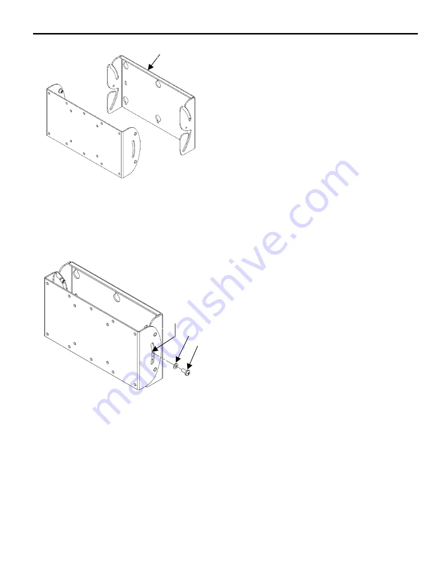
Figure 6. Assemble the Brackets 


Figure 7. Install the M5 Screw 

Mounting the Display on the Wall Bracket 
(Step 3) 

A. 

With an assistant (if necessary), lift the display up to the 
wall bracket (20) over the four mounting pins  
(see Figure 6. 

B. 

Align the mounting pins on the display with the slots in 
the wall bracket (20), and set the display into place. 

C. 

Verify that the display tilts on the wall bracket (20). 


Locking the Display on the Wall Bracket 
(Step 4) 

A. 

Assemble a washer (50) over each M5 screw (60). 
Install the two M5 (60) screw assemblies into the tapped 
holes located on the side of the wall bracket (20).  
See Figure 7. 

B. 

Set the display into the desired position. Tighten the M5 
screw (60) until friction holds the display stationary. 


Step 3 

20 

Tapped 
Hole


60

50

Step 4 

Summary of Contents for MSP-DCCGPM-210

Page 1: ...turing at 1 800 582 6480 or 952 582 6480 If a defect is discovered after Dell s initial 21 day Customer Satisfaction period Chief Mfg will at its option repair or repair the product at not charge provided it is returned during the warranty period Please note contact information for Chief Mfg listed below The tilt wall mount fits most 23 to 30 displays The mount is designed to adapt to VESA 200mm 1...

Page 2: ...quipment WARNING The combined weight of the display placed on the mount must not exceed 45 lbs 20 4kg the maximum load capacity of the mount WARNING Watch for pinch points Do not put your fingers between movable parts WARNING Make sure the mount is correctly oriented CAUTION Check the unit for shipping damage before you begin the installation CAUTION If your monitor uses a longer screw size other ...

Page 3: ...AD MACHINE SCREW M5 X 10MM 2 TILT ADJUSTMENT 70 PHILLIPS PAN HEAD MACHINE SCREW M4 X 12MM 6 FLUSH MOUNT 80 PHILLIPS PAN HEAD MACHINE SCREW M4 X 20MM USE WITH 90 OR 120 6 90 3 8 NYLON SPACER 6 100 PHILLIPS PAN HEAD MACHINE SCREW M4 X 30MM USE WITH 110 6 110 3 4 NYLON SPACER 6 120 1 8 NYLON SPACER USE WITH 90 6 RECESSED MOUNT Use M4 x 20mm screws 80 with spacers 90 for recessed mount applications Us...

Page 4: ... holes see Figure 1 NOTE This procedure applies to a minimum drywall thickness of inch 12 7 mm NOTE Mark the pilot holes as accurately as possible before drilling the holes The holes must be centered for the wall bracket to fit correctly on the wall D Using a 3 8 inch drill drill six pilot holes at the locations marked in Step 1 Option A E Install an anchor 30 in one of the pilot holes and tighten...

Page 5: ...t swing and extension radius B Position the wall bracket 20 as desired see Figure 3 NOTE Mark the mounting holes as accurately as possible before drilling the holes The holes must be centered for the wall bracket to fit correctly on the wall C Locate stud and using wall bracket 20 as a template at the desired height mark the location of the two center mounting holes D Using the two wood screws 40 ...

Page 6: ...use spacers The display is attached to the mount with six screws and four spacers For the procedure refer to page 7 CAUTION If monitor uses a screw size other than those included in the kit DO NOT use the screws provided Using the wrong screws could result in damage to your monitor Flushed Mount A Place the VESA bracket 10 on the display see Figure 4 B Align the hole pattern of your display with t...

Page 7: ...nd six spacers B Set six spacers over the four mounting holes on your monitor see Figure 5 C Set VESA interface bracket 10 on top of spacers and install six screws into the mounting holes of your display Table 2 200mm 100mm Compliant Displays OPTION SCREW QTY SPACER QTY 1 80 6 90 6 2 100 6 110 6 3 80 6 120 6 Table 3 75mm 100mm Compliant Displays OPTION SCREW QTY SPACER QTY 1 80 4 90 4 2 100 4 110 ...

Page 8: ... on the display with the slots in the wall bracket 20 and set the display into place C Verify that the display tilts on the wall bracket 20 Locking the Display on the Wall Bracket Step 4 A Assemble a washer 50 over each M5 screw 60 Install the two M5 60 screw assemblies into the tapped holes located on the side of the wall bracket 20 See Figure 7 B Set the display into the desired position Tighten...

Reviews: