background image

Installation Instructions

FWGSK110

7

4.

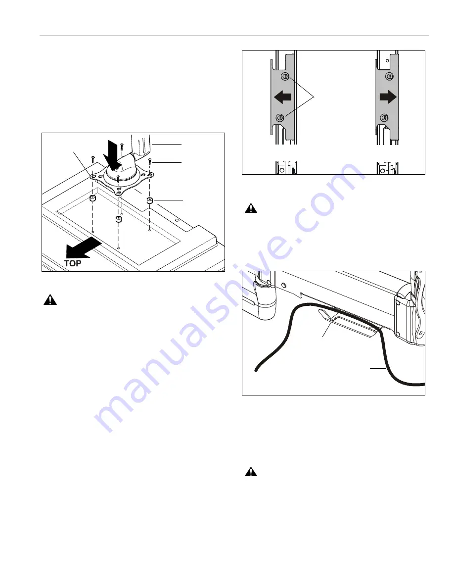
Select proper length spacer and screw. (See Figure 8)

NOTE:

All spacers used should be the same length.  If

the recess depths result in multiple spacer
lengths, then select the longer spacer.

5.

Place the four selected spacers over each of the mount
holes on the back of the display.

6.

Pick up and orient the mount (A) so that the mounting holes
in the Centris bracket are aligned with the holes in the
spacers; rotate the bracket as required. (See Figure 8)

Figure 8

WARNING:

IMPROPER INSTALLATION CAN LEAD TO

EQUIPMENT FALLING CAUSING SERIOUS PERSONAL
INJURY OR DAMAGE TO EQUIPMENT! Using screws of
improper size may damage your display!  Proper screws will
easily and completely thread into display mounting holes.

7.

Using Phillips screwdriver, install four screws (D or H)
through the mounting holes in Centris bracket, through the
spacers (F or G), and into the display.  (See Figure 8)

8.

Tighten all four screws.  Do not overtighten!

CABLE MANAGEMENT

1.

Attach all cables to display.

2.

Open the cable management bracket by sliding it towards
the edge of the arm (See Figure 9).

NOTE:

If necessary, cable management bracket attach

screws may be loosened using hex key (M).

Figure 9:

CAUTION:

Ensure that adequate cable slack exists for

movement of display, and that cables will not be pinched
when bracket is closed.

3.

Carefully insert cables into bracket (See Figure 10).

Figure 10:

4.

Close cable management bracket by sliding it back
towards the centerline of the arm.

NOTE:

If necessary, cable management bracket attach

screws may be tightened using hex key (M).

CAUTION:

Ensure that adequate cable slack exists for

movement of display, and that cables will not be pinched by
installation of cover (C) or screws (E).

5.

Carefully insert cables in cavity located in lower
portion of mount arm (See Figure 11).

6.

Using Phillips screwdriver, install cover (C) with two
screws (E). (See Figure 11)

(A) x 1

(D or H) x4

(F or G) x 4

Centris Bracket

OPEN Position

CLOSED Position

View from Bottom

Attach
Screws

Cable Path (typical)

NOTE: Display not shown for clarity.

Cable Management
Bracket (in open position)

Summary of Contents for FWGSK110

Page 1: ...de Instala o Istruzioni di installazione Installatie instructies Instructions d installation Small Flat Panel Steel Stud Wall Mount Spanish Product Description German Product Description Portuguese P...

Page 2: ...components are properly assembled and installed using the instructions provided WARNING Failure to provide adequate structural strength for the installation of this kit can result in serious personal...

Page 3: ...NSTALLATION AND PARTS TOGGLER x1 I M A 1 D 4 G 4 C 1 E 4 B 2 J 3 F 4 K 3 H 4 M 1 M4 x 12 L 3 1 2 x 3 4 1 4 20 x 1 3 4 3 16 M4 x 20 M4 x 20 1 4 1 2 x 3 8 1 4 20 SNAPTOGGLE BB flat panel wall mount N 1...

Page 4: ...that no other equipment should be mounted to the same stud Figure 1 Drywall 1 2 minimum Drywall Thickness Display Mount Installation Location FRONT Both Sides of Stud Must be centered on stud There m...

Page 5: ...andslidechannelthroughhole SeeFigure3 Figure 3 7 Holding plastic straps on anchor L pull anchor away from wall until channel rests flush behind wall making sure anchor channel is positioned vertically...

Page 6: ...ONLY as necessary to allow installation of Centris bracket 1 Ensure Centris bracket is able to swivel and tilt easily yet still be tight enough to hold display in desired position Adjust as required b...

Page 7: ...overtighten CABLE MANAGEMENT 1 Attach all cables to display 2 Open the cable management bracket by sliding it towards the edge of the arm See Figure 9 NOTE If necessary cable management bracket attac...

Page 8: ...tment screw counterclockwise towards the symbol If display rises on its own then rotate adjustment screw clockwise towards the symbol NOTE It may be necessary to raise or lower the height adjustable a...

Page 9: ...Installation Instructions FWGSK110 9...

Page 10: ...FWGSK110 Installation Instructions 10...

Page 11: ...Installation Instructions FWGSK110 11...

Page 12: ...5611 ZB EINDHOVEN The Netherlands P 31 0 40 2668620 F 31 0 40 2668615 Asia Pacific A Room 24F Block D Lily YinDu International Building LuoGang BuJi Town Shenzhen CHINA P 86 755 8996 9226 F 86 755 89...

Reviews: