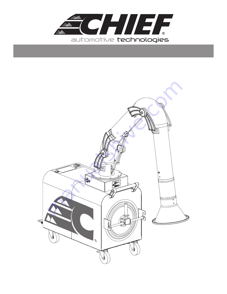
Chief Fume Extractor
l CHF1001, 7´ Arm Extractor • CHF1002, 10´ Arm Extractor
OWNER'S MANUAL
Page 1: ...Chief Fume Extractor l CHF1001 7 Arm Extractor CHF1002 10 Arm Extractor OWNER S MANUAL ...
Page 2: ...chnologies ORDER _ _____________________________________________________________________ UNIT MODEL ________________________________________________________________ UNIT SERIAL _________________________________________________________________ FILTER PART _ _______________________________________________________________ SYSTEM ACCESSORIES ____________________________________________________________...
Page 3: ... 4 6 1 Power Switch 4 6 2 Pressure Gauge 4 6 3 LOCATING EXTRACTION HOOD 4 6 4 EXTRACTION ARM DAMPER 5 6 5 START UP OPERATION 5 6 5 1 HOOD ACCESSORY KITS 5 6 6 SHUT DOWN AND STORAGE 5 7 0 User Servicing Instructions 5 7 1 Filter Replacement 5 7 2 ADJUSTING EXTRACTION ARM JOINTS 6 7 3 SPARK ARRESTOR 7 7 4 MOTOR SUPPLEMENTARY PROTECTION 8 7 5 ROUTINE MAINTENANCE 8 8 0 Troubleshooting Guide 9 9 0 Repl...
Page 4: ...s equipment Replace all access panels before operating Electrical connections should only be made by qualified personnel and be in accordance with local and national codes along with other applicable regulations Keep flammable materials and vapors such as gasoline away from the weld fume collector DANGER WARNING WARNING CAUTION C A U T I O N This is the safety alert symbol This symbol alerts you t...
Page 5: ...risk of fire electric shock or injury when using your air cleaner follow these basic precautions WARNING DANGER WARNING CAUTION C A U T I O N SÉCURITÉ Nous avons fourni des messages de sécurité importants dans ce manuel sur votre W Series de matériel d extraction des fumées Toujours lire et respecter tous les messages de sécurité C est le symbole d alerte de sécurité Ce symbole vous avertit d éven...
Page 6: ...n and identifies the key components of the system Over time collected fume builds up on the filter surface increasing the pressure loss across the filter This increased pressure causes a reduction in airflow and diminishes the extraction capacity of the system a pressure gauge located on the unit monitors the pressure and indicates when it is time to clean or replace the filter When the pressure d...
Page 7: ... or in an area where the unit will be prone to tipping Consideration should be given to routine product maintenance such as cleaning filter replacement and contaminant disposal The system should be moved using the push bar located on the front of the unit The extraction arm should not be used to pull or drag the unit Make sure that the front casters are in the locked position prior to operating th...
Page 8: ...eting the specifications identified above 4 Locate gas spring and spring mounting pins in loose parts kit box The mounting pins should be taped to the lid of the box Ensure that the pin and snap rings are within reach for installation 5 Install the gas spring in orientation shown onto the base tube spring bracket Install spring pin and retainer to secure the spring to the base tube spring bracket ...
Page 9: ...t alerts when action is required When the gauge reaches 4 W C or when airflow no longer can adequately extract fumes it is recommended to change or clean the filter 6 3 LOCATING EXTRACTION HOOD Do not place the system on a sloped surface or in an area where the unit will be prone to tipping The system should be moved using the push bar located on the front of the unit The extraction arm should not...
Page 10: ...on for approximately 1 minute before shutting down if additional arcs are not sensed 6 6 SHUT DOWN AND STORAGE To shut the fume extractor off place the main power switch into the off position Unplug the power cord and wrap the cord to the brackets located on the discharge side of the unit Compress the extraction arm into a compact position and pivot above the fume extractor unit Release the front ...
Page 11: ...d in the support brackets The flat surface of the door handle should be facing downward To close the filter access door push the door handle upward toward the unit The filter access door handle must be in a perpendicular orientation to door surface prior to being closed A flat solid section of door handle will be visible when door assembly is in the properly closed position If cam surface of the d...
Page 12: ...he inlet of the fume extractor immediately below the base of the extraction arm During operation spark embers or large particulate may accumulate on these baffles The baffles should be inspected and accumulated material should be removed on a regular basis To inspect the baffles unhook the two draw latches located on the left and right side of the box just below the inlet and pull the spark arrest...
Page 13: ...e unit mounted directly below the motor blower assembly To reset the circuit breaker remove the louvered discharge panel to gain access and then flip the breaker switch back to the closed setting 7 5 ROUTINE MAINTENANCE Disconnect electrical power prior to servicing equipment Take all necessary precautions including protective clothing such as eye protection ear plugs and gloves Daily Items Check ...
Page 14: ...nd clean as necessary Clean and remove any fume build up from the interior surfaces of the fume extractor and arm using a suitable vacuum or with warm water and detergent Semi Annual Items Remove filter and clean interior surfaces of filter cabinet Inspect the extraction arm swivel base Verify smooth rotation and that all mounting hardware is Inspect the extraction arm swivel base Verify smooth ro...
Page 15: ...me Extractor FIGURE 7 Fume Extractor Replacement Parts Detail 61 10085 9 0 REPLACEMENT PARTS 9 1 FUME EXTRACTOR REPLACEMENT PARTS Reserved space for fume extractor replacement parts table to be created by VSG 1 2 3 4 5 6 7 8 9 ...
Page 16: ...11 Revised 04 15 CHIEF Fume Extractor 9 2 EXTRACTION ARM REPLACEMENT PARTS 1 2 3 4 5 6 FIGURE 8 Extraction Arm Replacement Parts 61 10081 ...
Page 17: ...SSORY CONTROLS 14AWG H BLK 14AWG A RED 2 RED 1 BLK BLK BLK GRN GRN A RED 16AWG H BLK 16AWG N WHT 16AWG G GRN 16AWG LIGHT KIT MOUNTED ON SWING ARM HOOD LIGHTKIT PCB ACCESSORY PLATE RELAY OUT NEUTRAL GND 12VAC GRN WHT RED BLK GRN WHT RED BLK B R W G SEE NOTE 4 04 001493 WIRING DIAGRAM CB1 15A CR1 1 4 BLOWER CR1 AC CR1 5 6 G G G G N N N N A A A A H H H H 4 4 4 4 3 3 3 3 2 2 2 2 1 1 1 1 B R W G 1 2 OX...
Page 18: ...This page intentionally left blank ...
Page 19: ...This page intentionally left blank ...
Page 20: ...attempted by others CHIEF AUTOMOTIVE TECHNOLOGIES DOES NOT ASSUME RESPONSIBILITY FOR ANY DEATH INJURY OR PROPERTY DAMAGE RESULTING FROM THE OPERATOR S NEGLIGENCE OR MISUSE OF THIS PRODUCT OR ITS ATTACHMENTS CHIEF MAKES NO WRITTEN EXPRESS OR IMPLIED WARRANTY WHATSOEVER OF MERCHANTABILITY OR FITNESS FOR A PARTICULAR PURPOSE OR OTHERWISE REGARDING THE EQUIPMENT OR ANY PART OF THE PRODUCT OTHER THAN T...