background image

Page 9

!

DANGER

Low discharge pressure

1. Reduce air demand or use a compressor
    with more air capacity.
2. Listen for air leaks. Apply a soap solution
    to all fittings and connections. Bubbles
    will form at points of leakage. Tighten
    or replace fittings or connections.
3. Clean or replace air filter.
4. Replace necessary gaskets.
5. Remove head and inspect for broken or
    misaligned valves.  Replace valves, if
    necessary.

                                         Install a new head gasket
                                         each time head is removed

1. Tighten drive pulley or flywheel bolt.
2. Check for proper oil level.  Low or dirty
    oil may cause bearing damage.
3. Replace connecting rod and/or connecting
    rod bearings.
4. Replace check valve.
                                   

                                        with air pressure in tank

1. Replace with new piston rings.
2. Clean or replace air filter.
3. Drain oil to proper oil level.
4. Use a quality non-detergent 30 or 40wt
    oil specified for each model (Page 4).

1. Drain tank at least once per day.
2. Add an inline filter to reduce moisture in
    the air line.

1. Check voltage with volt meter across both
    legs of incoming power. Check reset button
    on motor.
2. Repair or replace pressure switch.
3. Replace check valve or pressure switch.


Do not remove check valve

                                        with air pressure in tank

1. Make sure the breaker is sized properly. 
    See page 6 in this manual.
2. Check voltage with volt meter across both
    legs of incoming power.
3. Replace motor.
4. Check all electrical connections.
5. Adjust or replace pressure switch.
6. Replace check valve.


Do not remove check valve

                                        with air pressure in tank

1. Replace check valve.


Do not remove check valve

                                        with air pressure in tank

2. Tighten or replace fittings or connections.
3. Replace tank. Do not attempt to repair tank.

Do not remove check valve

1. Compressor too small for 
    application
2. Air leaks

3. Restricted intake air
4. Blown gasket(s)
5. Broken or misaligned valves

!

DANGER

!

DANGER

!

DANGER

1. Loose drive pulley or flywheel
2. Low on oil

3. Worn connecting rod or 
    connecting rod bearing
4. Noisy check valve

1. Worn piston rings
2. Restricted intake air
3. Too much oil in compressor
4. Incorrect oil viscosity

1. Normal. Amount of water will
    increase as humidity in the
    air increases.

1. Low voltage

2. Malfunctioning pressure switch
3. Malfunctioning check valve

1. Incorrect breaker size

2. Low voltage

3. Malfunctioning motor
4. Loose electrical connections
5. Malfunctioning pressure switch
6. Malfunctioning check valve

Tank does not hold 
pressure when not
running and shut off 
valve is closed

Breaker or reset 
repeatedly trips

Will not run or motor 
hums

Water in tank and/or 
discharge line

Excessive oil carryover

Excessive noise 
“knocking”

TROUBLESHOOTING GUIDE

1. Malfunctioning check valve

2. Loose fittings or connections
3. Crack or pin hole in tank

CAUTION

!

Summary of Contents for RCP Series

Page 1: ...For questions concerning this air compressor please call 866 869 3114 Rev 0413 RCP Series Air Compressor Manual Part 1312100412 ...

Page 2: ...llow Safety Precautions for Electrical Connection Plan Ahead to Protect Your Eyes Hands Face Ears When Operating 4 Spraying Precautions Perform These Maintenance Operations 5 Typical Compressor Installation Glossary 6 Wiring 7 Starting the Compressor 8 QP Compressor 9 Troubleshooting 10 Troubleshooting Cont Tank Warning Parts Back Warranty Statement ...

Page 3: ...les of safe operation should use the air compressor 1 Read the instruction manual carefully before attempting to assemble disassemble or operate your system Be thoroughly familiar with the controls and the proper use of the equipment 2 Review and understand all safety instructions and operating procedures in this manual 3 Review the maintenance methods for this compressor See Maintaining Your Comp...

Page 4: ...y of an operating compressor 9 Do Not locate the compressor air inlet near steam paint spray sandblasting areas or any other source of contamination The debris could damage the motor and pump Never use plastic PVC pipe for compressed air Serious injury or death could result Never use the shipping skid for mounting the compressor This compressor is not intended for outdoor installation Never instal...

Page 5: ...ough to cause injury Never operate the compressor without a beltguard The compressor can start auto matically without warning Personal injury or property damage could occur from contact with moving parts The compressor may be hot even if the unit is stopped Use of a mask or respirator per chemical manufacturers instructions may be neces sary if there is a chance of inhaling toxic fumes Read mask a...

Page 6: ...ank Welding drilling or any other modification will weaken the tank resulting in damage from rupture or explosion Always replace worn cracked or damaged tanks 3 Clean electrical equipment with an approved cleaning agent such as a dry non flam mable cleaning solvent Daily Check oil level at sight glass Oil level should be 1 2 to slightly higher in the oil sight glass Drain moisture from tank Verify...

Page 7: ...which automatically controls the on off cycling of the compressor It stops the compressor when the cut off pressure in the tank is reached and starts the compressor when the air pressure drops below the cut in pressure PSI Pounds per Square Inch Measurement of the pressure exerted by the force of air The actual psi is measured by a pressure gauge on the compressor Pump Device which produces the co...

Page 8: ...must be properly grounded Ground connections should be connected at the grounding screw Overheating short circuiting and fire damage will result from inadequate wiring WARNING WARNING WARNING CAUTION WIRING Single Phase Ground Incoming power should be connected to L1 and L2 at the Top of the Magnetic Starter Three Phase Ground Incoming power should be connected to L1 L2 L3 at the Top of the Magnet...

Page 9: ... Prior to actually running the compressor check the following items Crankcase oil Make sure the sight glass shows full or slightly above Make sure all rags tools oil etc are away from the unit Open the air system to free it of any pressure Switch the compressor on for a few revolutions to make sure the rotation is correct Correct rotation is clockwise when facing the sight glass on the pump Operat...

Page 10: ...g to allow for the oil to flow completely into the switch Please Note If overfilled oil will flow out of the oil vent hole Thermal Protection QP Models If the cooling fan were to fail or internal temperature were to reach 180 F the QP models are outfitted with a thermal fuse When tripped the fuse can be reset The canopy will need to be removed to reset the thermal fuse Location of Fuse Inside Cano...

Page 11: ...anual 2 Check voltage with volt meter across both legs of incoming power 3 Replace motor 4 Check all electrical connections 5 Adjust or replace pressure switch 6 Replace check valve Do not remove check valve with air pressure in tank 1 Replace check valve Do not remove check valve with air pressure in tank 2 Tighten or replace fittings or connections 3 Replace tank Do not attempt to repair tank Do...

Page 12: ...cooling surfaces of dirt and dust 3 Install compressor in an area with adequate cool dry air 1 Malfunctioning check valve Overheating TROUBLESHOOTING GUIDE Continued Pressure switch un loader constantly leaking air 1 Replace check valve if unloader bleeds constantly Do not remove check valve with air pressure in tank DANGER Pressure switch not unloading 1 Malfunctioning pressure switch DANGER Exce...

Page 13: ...ea before attempting to drain mois ture from the tank s Reduce the air pressure in the tank to 30 PSIG by pulling the pressure relief valve ring refer to Fig 3 4 Checking Pressure Relief Valves Relieving System Pres sure Step 3 Slowlyopenthedrainvalveandallowthemoistureandairmixture to drain from the tank Step 4 Once the moisture has been completely drained close the drain valve Oil and moisture r...

Page 14: ...n Intervals relative information Refer to federal state or provincial orlocalcodesformandatoryairtank Fig 3 5 Recommended Air Tank Inspection Intervals Tank Capacity Horizontal or Vertical Minimum Allowable Wall Thickness Visually Inspect Head Shell 30 Gal Horizontal 094 106 Yearly 60 Gal Horizontal 109 135 Yearly 60 Gal Vertical 109 111 Yearly 80 Gal Horizontal 109 135 Yearly 80 Gal Vertical 131 ...

Page 15: ...ch Discharge Line Ball Valve Inlet Filter Water Tank Drain Compressor Engine Tank Pressure Gauge Inlet Filter Water Tank Drain Pilot Unloader Valve Idle Control Drive Belt Belt Guard Drive Belt Magnetic Starter Pressure Gauge Ball Valve Electric Gas Drive Page 11 ...

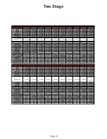
Page 16: ...witch 1312100407 1312100407 Unloader Pilot Valve 1312100496 1312100496 1312100495 1312100495 1312100495 Safety Valve 1312100005 1312100005 Safety Valve 1312100005 1312100005 9710533300 9710533300 9710533300 Pressure Gauge 1312100378 1312100378 Pressure Gauge 1312100378 1312100378 1312100378 1312100378 1312100378 Discharge Tube 1312100206 1312100206 Discharge Tube 1312100205 1312100205 1312100205 1...

Page 17: ...1312100110 Beltguard Aftercooler N A N A N A N A N A N A N A N A N A N A RCP 7581HS RCP 7583VS 4 RCP 7583HS 4 RCP 7581V RCP 7581H RCP 7583V 4 RCP 7583H 4 RCP 10123VS 4 RCP 10123HS 4 RCP 10123V 4 Pump 4116090019 4116090019 4116090019 4116090019 4116090019 4116090019 4116090019 4116090148 4116090148 4116090148 Motor 1312100400 1312100398 1312100397 1312100400 1312100397 1312100397 1312100397 1312100...

Page 18: ...100406 1312100406 1312100406 1312100406 1312100406 1312100406 1312100406 1312100406 Safety Valve 9710533300 9710533300 9710533300 9710533300 9710533300 9710533300 9710533300 9710533300 9710533300 9710533300 9710533300 Pressure Gauge 1312100378 1312100378 1312100378 1312100378 1312100378 1312100378 1312100378 1312100378 1312100378 1312100378 1312100378 Discharge Line 1312100211 Lt 1312100212 Rt 131...

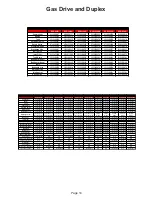
Page 19: ...0 Tank Drain 1312100110 1312100110 1312100110 1312100110 Ball Valve 1312100163 1312100163 1312100163 1312100163 Disch Line 1312100198 1312100198 1312100198 1312100198 Inlet Filter 1312100097 1312100097 1312100097 1312100097 Low Oil Switch 1312100014 1312100014 1312100014 1312100014 Blower 1312100088 1312100088 1312100088 1312100088 Belt Guard 1312100148 1312100148 1312100148 1312100148 1312100150 ...

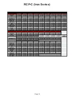
Page 20: ...0169 1312100169 1312100169 1312100172 1312100172 1312100172 RCPC10123V RCPC10123V4 RCPC10123H RCPC10123H4 RCPC20123D RCPC20123D4 RCP20203D RCP20203D4 Compressor 1312202700 1312202700 1312202700 1312202700 1312202700 1312202700 1312202700 1312202700 Motor 1312101600 1312101600 1312101600 1312101600 1312101600 1312101600 1312101600 1312101600 Belt Guard 1312100983 1312100983 1312100983 1312100983 13...

Page 21: ......

Page 22: ......

Page 23: ......

Page 24: ......

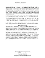
Page 25: ...d for the period of time provided above THE COMPANY MAKES NO OTHER WARRANTY OR REPRESENTATION OF ANY KIND WHATSOEVER EXPRESSED OR IMPLIED EXCEPT THAT OF TITLE AND ALL IMPLIED WARRANTIES OF MERCHANTABILITY AND FITNESS FOR A PARTICULAR PURPOSE ARE HEREBY DISCLAIMED THIS WARRANTY SUPERSEDES ALL PREVIOUS WARRANTY STATEMENTS Correction by the Company of non conformities whether patent or latent in the ...

Reviews: