Page 9
For technical questions, please call 1-800-444-3353.
SKU 68821
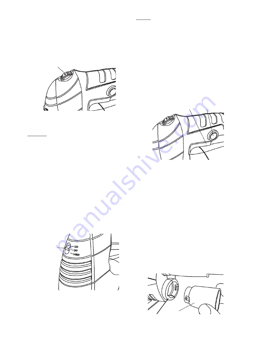
Adjusting Jigsaw Speed
1. The Jigsaw’s speed can be adjusted between
500 and 3,000 strokes per minutes.
2. To adjust speed, turn the Speed Switch from
1 (the slowest speed) to 6 (the fastest speed).
See Figure 3, below.
Figure 3
Speed Switch
3. Use higher speeds to cut workpieces faster.
NOTICE:
Refer to the Blade Selection
chart on page 7 to verify you are using the
correct speed with the appropriate blade.
Otherwise blade damage can occur.
General Operating Instructions
1. Plug the Power Cord into the nearest
120 volt, grounded, electrical outlet.
2. Position the saw blade of the Jigsaw about
1/2” from the beginning cut line on the
workpiece. Do not allow the saw blade
to come in contact with the workpiece.
3. Turn the Laser Switch (46) to its “LASER”
position, and align the laser beam with the cut
line on the workpiece. See Figure 4, below.
Figure 4
Laser
Switch
(46)
NOTE:
The Jigsaw is equipped with
both a Laser Guide and an LED light.
However, both cannot be used at the same time.
The Laser Switch can only be set in the
Laser setting OR the LED light setting.
4. To turn off the Laser or LED, slide the
Laser Switch to the OFF position.
5. Squeeze the Trigger (16) to turn on the
Jigsaw. If operating the Jigsaw for an
extended period of time, depress the Trigger
Lock (located above the Power Switch) to
lock the Trigger in its “ON” position.
See Figure 5, below.
Figure 5
Trigger
(16)
Trigger
Lock
6. Allow the Saw Blade to stroke at full speed
before slowly feeding it into the workpiece.
7. Make sure to hold the Jigsaw firmly
with both hands to avoid kickback.
Then, finish making the cut.
Dust Chute and Dust Blower
1. The Jigsaw is supplied with a Dust Chute
adapter for a vacuum. It is attached
to the Dust Chute Connector located
at the back end of the housing.
2. To fasten the Dust Chute (sold separately)
in place, align the pins on Dust Chute with
slots in Connector. Push Dust Chute in and
turn clockwise to lock. See Figure 6, below.
Dust
Chute
Connector
Figure 6


