


SKU 66523
For technical questions, please call 1-800-444-3353.
Page 25
Freight Tools Customer Service Department at 1-800-444-
3353.
Harbor Freight Tools Emission Control defects
Warranty Provisions
Length of Coverage
1.
HFT warrants to a first retail purchaser and each sub
-
sequent purchaser that the engine is free from defects
in materials and workmanship that cause the failure of
warranted parts for a period of two (2) years after the
date of delivery to the first retail purchaser.
No Charge Repair or Replacement
1.
Repair or replacement of any warranted part will be
performed at no charge to the owner if the work is per-
formed through a warranty station authorized by HFT. For
emissions warranty service, contact the HFT Customer
Service Department at 1-800-444-3353.
Consequential damages Coverage
1.
Coverage under this warranty shall also extend to the
failure of any engine components caused by the failure
of any warranted part while it is still covered under this
warranty.
Coverage Exclusions
1.
Warranty claims shall be filed in accordance with the
provisions of the HFT warranty policy explained in the
box at the top of the previous page. HFT shall not be
liable for any loss of use of the engine, for any alternative
usage, for any damage to goods, loss of time, or incon-
venience. Warranty coverage shall also be excluded
for any part which fails, malfunctions, or is damaged
due to failure to follow the maintenance and operating
instructions set forth in the Owner’s Manual including,
but not limited to:
Use of parts which are not authorized by HFT
a.
Improper installation, adjustment or repair of the
b.
engine or of any warranted part unless performed
by an authorized warranty center
Failure to follow recommendations on fuel use con-
c.
tained in the Owner’s Manual
Improper or inadequate maintenance of any war-
d.
ranted parts
Repairs performed outside of the authorized war-
e.
ranty service dealers
Alterations by changing, adding to or removing parts
f.
from the engine.
Service and Maintenance
1.
Component parts which are not scheduled for replace-
ment as required maintenance or are scheduled only
for regular inspection to the effect of “repair or replace
as necessary” are warranted for the warranty period.
Any warranted part which is scheduled for replacement
as required maintenance is warranted for the period of
time up to the first scheduled replacement point for that
part. Any replacement part, provided it is equivalent in
durability and performance, may be used in performance
of maintenance or repairs. The owner is responsible
for commissioning a qualified technician/mechanic
to perform all required maintenance, as outlined in
the Inspection, Cleaning, and Maintenance section
in this manual.
Warranted Parts
1.
Fuel Metering System
1.
Carburetor and its internal parts.
i.
Fuel pump (if so equipped).
ii.
Cold start enrichment system.
iii.
Air Induction System
1.
Intake pipe/manifold.
i.
Air cleaner.
ii.
Ignition System
1.
Spark plug.
i.
Magneto ignition system.
ii.
Catalyst System (if so equipped)
1.
Exhaust pipe stud.
i.
Muffler.
ii.
Catalytic converter (if so equipped).
iii.
Miscellaneous Items Used in Above Systems
1.
Vacuum, temperature and time sensitive
i.
valves and switches.
Hoses, belts, connectors, and assem-
ii.
blies.
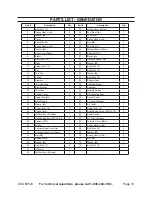
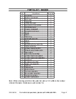
PLEASE REAd THE
FOLLOWING CAREFuLLY
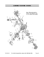
THE MANUFACTURER AND/OR DISTRIBUTOR HAS
PROVIDED THE PARTS LIST AND ASSEMBLY DIAGRAM IN
THIS MANUAL AS A REFERENCE TOOL ONLY. NEITHER
THE MANUFACTURER OR DISTRIBUTOR MAKES ANY
REPRESENTATION OR WARRANTY OF ANY KIND TO
THE BUYER THAT HE OR SHE IS QUALIFIED TO MAKE
ANY REPAIRS TO THE PRODUCT, OR THAT HE OR
SHE IS QUALIFIED TO REPLACE ANY PARTS OF THE
PRODUCT. IN FACT, THE MANUFACTURER AND/OR
DISTRIBUTOR ExPRESSLY STATES THAT ALL REPAIRS
AND PARTS REPLACEMENTS SHOULD BE UNDERTAKEN
BY CERTIFIED AND LICENSED TECHNICIANS, AND
NOT BY THE BUYER. THE BUYER ASSUMES ALL RISK
AND LIABILITY ARISING OUT OF HIS OR HER REPAIRS
TO THE ORIGINAL PRODUCT OR REPLACEMENT
PARTS THERETO, OR ARISING OUT OF HIS OR HER
INSTALLATION OF REPLACEMENT PARTS THERETO.
Record Product’s Serial Number Here:
________________________________
Note:
If product has no serial number, record month and
year of purchase instead.
Note:
Some parts are listed and shown for illustration
purposes only, and are not available individually as
replacement parts.


