background image

Page 8

For technical questions, please call 1-800-444-3353.

Item 60428 


SAFET

y

Op
ERA
TION

M

AINTENAN

c

E

SETU
p

Operating Instructions

  Read the ENTIRE IMpORTANT SAFETy INFORMATION section at the beginning of this 

manual including all text under subheadings therein before set up or use of this product.

Tool Set Up

TO pREVENT SERIOUS INJURy FROM AccIDENTAL OpERATION: 

Make sure that the power Switch is in the off-position and unplug the tool from 

its electrical outlet before performing any procedure in this section.

Attachment Installation

1.  Use the Hex Key (1) to remove the Cap Screw (2) 

and Washer (3) from the end of the Spindle (4).

2.  Install the desired accessory (sold separately) 

by placing the accessory’s mounting holes 

against the fitting pins on the Spindle.

cAUTION!

  When attaching a Scraper Blade, Wood 

Cutting Blade, or Half-Moon Cutting Blade (all sold 

separately), orient the accessory so that the blade 

faces AWAY from the handle to avoid injury.

3.  Replace the Cap Screw and Washer while holding 

the accessory.  Make sure the cupped side of 

the Washer is toward the tool.  While holding the 

attachment over the pins on the tool, tighten the 

Cap Screw onto the Spindle using the Hex Key.  

Torque snugly (approximately 10 ft-lb).

cAUTION!

  Make sure that the accessory is 

held securely in place by the four fitting pins on 

the Spindle as the Cap Screw is tightened.

Washer (3)

cutter Blade

Spindle (4)

cap Screw (2)

Figure B:  Example of Installed Attachment

4.  After securing, the attachment should not move 

on the Spindle.  If it can move with the power 

off, remount it, making sure that the holes on the 

attachment line up with the pins on the Spindle.  

Tighten the Cap Screw securely.

Note:

  For sanding, first attach a Sanding Pad 

(sold separately) to the tool, then align a sheet of 

Sandpaper (sold separately) over the pad and press 

into place.  Once a Sandpaper corner becomes worn, 

turn it 120° or replace the sheet with a new one.

General Operating Instructions

1.  Make sure that the Power Switch is in 

the off-position, then plug in the tool.

2.  Hold the Tool with both hands and slide 

the Power Switch forward to activate.

3.  Do not allow contact between Sandpaper, Scraper, 

or Blade and workpiece until tool is at full speed.

4.  Avoid contact with foreign objects such as metal 

screws and nails when sanding, scraping, or cutting.

5.  Do not apply excessive pressure on the Tool.   

Allow the Tool to do the work.

6.  When finished, slide the Power Switch to OFF.  Allow 

the tool to stop completely before setting it down.

7.  To prevent accidents, turn off the tool and 

unplug it after use.  Clean, then store the 

tool indoors out of children’s reach.

Summary of Contents for 60428

Page 1: ......

Page 2: ...ation which if not avoided could result in minor or moderate injury Addresses practices not related to personal injury IMPORTANT SAFETY INFORMATION General Power Tool Safety Warnings Read all safety warnings and instructions Failure to follow the warnings and instructions may result in electric shock fire and or serious injury Save all warnings and instructions for future reference The term power ...

Page 3: ...e off position before connecting to power source picking up or carrying the tool Carrying power tools with your finger on the Power Switch or energizing power tools that have the Power Switch on invites accidents 4 Remove any adjusting key or wrench before turning the power tool on A wrench or a key left attached to a moving part of the power tool may result in personal injury 5 Do not overreach K...

Page 4: ... tool maintain a firm grip on the tool with both hands to resist starting torque 6 Do not leave the tool unattended when it is plugged into an electrical outlet Turn off the tool and unplug it from its electrical outlet before leaving 7 This product is not a toy Keep it out of reach of children 8 People with pacemakers should consult their physician s before use Electromagnetic fields in close pro...

Page 5: ...al If any abnormal vibration occurs stop use immediately SAVE THESE INSTRUCTIONS Grounding TO PREVENT ELECTRIC SHOCK AND DEATH FROM INCORRECT GROUNDING WIRE CONNECTION Check with a qualified electrician if you are in doubt as to whether the outlet is properly grounded Do not modify the power cord plug provided with the tool Never remove the grounding prong from the plug Do not use the tool if the ...

Page 6: ...wire size required See Table A 5 If you are using one extension cord for more than one tool add the nameplate amperes and use the sum to determine the required minimum cord size See Table A 6 If you are using an extension cord outdoors make sure it is marked with the suffix W A W in Canada to indicate it is acceptable for outdoor use 7 Make sure the extension cord is properly wired and in good ele...

Page 7: ... page 10 Functions Spindle Power Switch Blade sold separately Hex Key Figure A Workpiece and Work Area Set Up 1 Designate a work area that is clean and well lit The work area must not allow access by children or pets to prevent distraction and injury 2 Route the power cord along a safe route to reach the work area without creating a tripping hazard or exposing the power cord to possible damage The...

Page 8: ...proximately 10 ft lb CAUTION Make sure that the accessory is held securely in place by the four fitting pins on the Spindle as the Cap Screw is tightened Washer 3 Cutter Blade Spindle 4 Cap Screw 2 Figure B Example of Installed Attachment 4 After securing the attachment should not move on the Spindle If it can move with the power off remount it making sure that the holes on the attachment line up ...

Page 9: ...k that cord is plugged in 2 Check power at outlet If outlet is unpowered turn off tool and check circuit breaker If breaker is tripped make sure circuit is right capacity for tool and circuit has no other loads 3 Turn off tool and allow to cool Press reset button on tool 4 Have technician service tool Tool operates slowly 1 Forcing tool to work too fast 2 Extension cord too long or cord diameter t...

Page 10: ...OF HIS OR HER INSTALLATION OF REPLACEMENT PARTS THERETO Parts List Part Description Qty 1 Hex Key 1 2 Cap Screw M8x12 1 3 Washer 1 4 Spindle 1 5 Screw M4x14 4 6 Spring Washer 4 7 Front Cover 1 8 Bearing 6000 1 9 Locking Ring 1 10 Bushing 2 11 Block 1 12 Brass Bushing 1 13 Tapping Screw ST4x22 4 14 Front Housing 1 15 Gearbox Back Cover 1 16 Screw M4x10 2 17 Locking Ring 1 18 Bearing 18 1 19 Bearing...

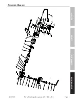
Page 11: ...ety Operation Maintenance Setup Assembly Diagram 1 2 3 4 5 6 7 8 9 10 11 12 13 14 15 16 17 18 19 23 2 7 26 28 29 32 33 34 36 31 35 39 30 37 37 38 20 21 22 24 25 1 2 3 4 5 6 7 8 9 10 11 12 13 14 15 16 17 18 19 23 2 7 26 28 29 32 33 34 36 31 35 39 30 37 37 38 20 21 22 24 25 20 ...

Page 12: ... the exclusion or limitation of incidental or consequential damages so the above limitation of exclusion may not apply to you THIS WARRANTY IS EXPRESSLY IN LIEU OF ALL OTHER WARRANTIES EXPRESS OR IMPLIED INCLUDING THE WARRANTIES OF MERCHANTABILITY AND FITNESS To take advantage of this warranty the product or part must be returned to us with transportation charges prepaid Proof of purchase date and...

Reviews: