Chevrolet 1997 Corvette Complete Manual Download Page 36

1997/98 Chevrolet Corvette


Collision Repair

3-35

Rear Bumper Impact Bar

,,

,

,

,

,,

,

,

View A

40mm

50mm

15mm

30mm

50mm

40mm

View A

C of 
vehicle

L

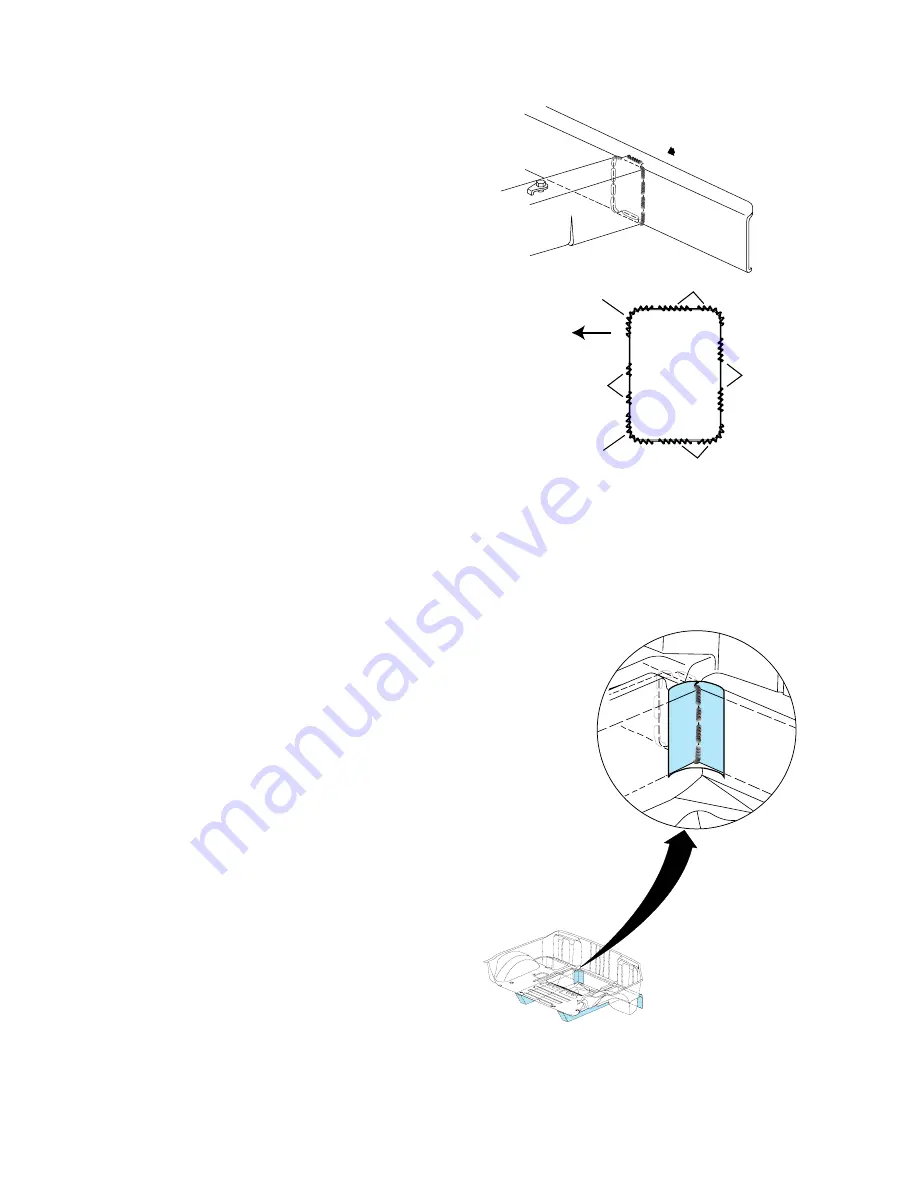
Fig.␣ 3.74 — Weld Perimeter of Joint, as Indicated

,

,,

,

,

,

,

,

,

,

,

,

,

,

,

,

,

,

,

Fig.␣ 3.75 — Prime Bare Metal Areas

Before Installing Window Cutouts

2

Temporarily position the impact bar and
scribe lines into the primer indicating where
the welds will be made. Remove the primer
from the areas to be MIG welded by sanding
with 80-grit paper on a ‘Dual-Action’ sander
(DA). Do Not use a grinder to remove the
primer.

3

Prepare all bare metal surfaces and apply
weld-through primer as necessary. Be sure to
apply primer to the inside of the ‘fishmouth’
area also.

4

Position the bumper impact bar using
three-dimensional measuring equipment and
install per the original weld locations. Stitch
weld around the ‘fishmouth’ joint. If not trace
of the original welds are present, use
Fig.␣ 3.74 as a guide for welding the side rails
to the impact bar. This weld pattern will
create a solid weld joint with minimal heat
distortion.

5

Clean and prepare all welded surfaces,
use 3M’s Scotch-Brite Clean-N-Strip Discs
(disc P/N 07460, mandrel P/N 07491), or
equivalent (Fig.␣ 3.75).

Important: Prior to refinishing, refer to
GM P/N 4901 Refinish Manual for
recommended products.

6

Apply approved anti-corrosion primer.

Notice: DO NOT top-coat any bonding
surfaces.

Notice: Top surface of impact bar (where
it is to be bonded to the rear
compartment panel), must not be
top-coated, see Fig.␣ 3.73. The bonding
area must remain a ‘primer only’ surface

7

Apply 50mm (2 inch) wide tape over the
‘windows’ cut in the rear compartment panel,
from outside the vehicle. Apply adhesive to
the inside of the tape backer, and install the
previously cut-out pieces in their original
locations (Fig.␣ 3.76). (

Refer to SMC repair

procedures.)

Important: Use US Chemical and Plastics
82014B System 2000 Structural Adhesive,
a PLIOGRIP

®

 adhesive manufactured by

Ashland Chemical Company, or equivalent.
Note the 9 minute working time and 1
hour cure time.

Summary of Contents for 1997 Corvette

Page 1: ...3 4 Rail Underbody Side Assembly 3 6 Front Side Door Opening Assembly 3 17 Windshield Frame Assembly 3 19 Front Floor Panel 3 22 Roof Bow Service 3 24 Rear Compartment Panel 3 25 Rear Compartment Pane...

Page 2: ...1 Panel Identification POLYCARBONATE TRANSLUCENT TARGA TOP 1 RRIM REINFORCED REACTION INJECTION MOLDED 2 TSGS TWO SIDED GALVANIZED STEEL 3 UHSS ULTRA HIGH STRENGTH STEEL 4 SMC SHEET MOLDED COMPOUND 5...

Page 3: ...m Kent Moore Tools Riv Nut Kit P N J42151 8MS if needed REMOVE OR DISCONNECT 1 Remove all panels and components to gain access to the impact bar This includes the bumper cover impact absorbers and fog...

Page 4: ...primer to the inside of the fishmouth area also Notice When installing the replacement bumper bar weld the sides first in order to ensure uniform contact with the frame rails 4 Position the bumper imp...

Page 5: ...MC body panels until the frame rails have been replaced or repaired mounting SMC panels requires the rails to be positioned accurately REMOVE OR DISCONNECT 1 Remove all panels and components to gain a...

Page 6: ...se paint stir sticks or equivalent and shim according to body dimensions and body panel alignment 1 Remove all remaining adhesive and scuff all bonding surfaces to ensure proper adhesion Refer to SMC...

Page 7: ...panels to fit properly The one piece frame rails have 18x35 shipping slots that are used to secure a damaged vehicle to a bench for holding and dimensional straightening Use Kent Moore tools frame ad...

Page 8: ...Technique as Indicated Underbody Side Rail Sectioning The two methods recommended for frame rail sectioning are the sleeved butt joint and the offset lap joint The sleeved butt joint sectioning proce...

Page 9: ...are in place check the fit of the service part Grind sleeve as necessary to allow for accurate alignment of the new part Notice Retain a gap of one and one half times the metal thickness at the butt...

Page 10: ...to create additional adjustment if necessary Do not exceed 100mm 4 inch overlap for offset lap joint repairs 6 Drill three 8mm 5 16 inch holes through each of the sides and two holes each in the top...

Page 11: ...nt frame rail end is kinked or damaged beyond repair forward of the front crossmember The service part must be cut from an underbody side rail assembly Notice Use the sleeved butt joint method to inst...

Page 12: ...t of dash panel for cracks or areas that may need to be re sealed Fig 3 22 Refer to SMC Repair Procedures Notice Use the Offset Lap Joint method to perform front rail repairs REMOVE OR DISCONNECT Noti...

Page 13: ...create a 2 flange Fig 3 24 Cut stitch welds along the rail and drill out the resistance welds along the tunnel brace Remove floorpan extension panel 6 Determine the location to perform the sectioning...

Page 14: ...not combine paint systems Refer to paint manufacturer s recommendations 5 After sectioning repairs are completed attach panels and components as necessary Mid Rail Repair When most of the front or rea...

Page 15: ...Rail Repair When damage to the frame rail is limited to the portion rearward of the seat back area The seat back sectioning area is exposed by modifying or removing close out panels and tunnel braces...

Page 16: ...the lock pillar can be a fire hazard Avoid welding to the lock striker pillar 3 Using a die grinder cut along the edge of tape line Cut stitch welds along the rail and drill out the resistance welds...

Page 17: ...during installation 1 Determine sectioning joint location within the recommended area see Sleeved Butt Joint Method Repair Procedures 2 Perform sleeved butt joint sectioning as required Refer to Sleev...

Page 18: ...pulling and straightening is required Fig 3 33 Notice The frame rails and bumper impact bars must be serviced as required and returned to three dimensional coordinates before any SMC repairs are atte...

Page 19: ...with the front hinge pillar Fig 3 35 6 Remove panel assembly and apply a consistent bead of adhesive 10mm in diameter to the front body hinge pillar and top surface of rail and to all areas originall...

Page 20: ...hield frame assembly includes removal of the windshield the instrument panel assembly and the upper plenum REMOVE OR DISCONNECT 1 Remove all panels and components to gain access to the windshield asse...

Page 21: ...bonds and remove brace from vehicle 8 Remove bolts attaching windshield frame to the front hinge pillars see Fig 3 38 9 Heat and break loose adhesive bonds along front and rear edges of the front body...

Page 22: ...area that the cross car brace bonds to the center tunnel assembly and install brace and bolt into place 7 Attach all instrument panel supports to the windshield frame assembly service part 8 Apply adh...

Page 23: ...frame rail and seat mounting brace restore as much of the damage as possible to specifications using three dimensional measuring procedures 3 Remove the side reinforcement bonded to the floor panel an...

Page 24: ...ply adhesive to the floor panel support bracket and install to attach floor panel to tunnel as in Fig 3 47 Apply adhesive to the floor panel brace and install as shown in Fig 3 48 Screw the ends of th...

Page 25: ...ive Fig 3 50 The Roof Bow Cover overlaps the Rear Compartment Panel Frame which should be sectioned if the Roof Bow Cover is not damaged Refer to Rear Compartment Panel Frame Service Procedures Import...

Page 26: ...the damage as possible to specifications using three dimensional measuring procedures Notice Use Kent Moore Tools Frame Adapter Clamp P N J42058 to secure the vehicle if pulling and straightening is...

Page 27: ...ide of the lock pillars as well as over the fuel filler neck Important Use US Chemical and Plastics 82007B System 2000 Structural Adhesive a PLIOGRIP adhesive manufactured by Ashland Chemical Company...

Page 28: ...ct and restore as much of the damage as possible to specifications using three dimensional measuring procedures Notice The frame rails and bumper impact bars must be serviced as required and returned...

Page 29: ...e where sectioning procedures are being performed Notice Take care not to damage the frame rails when sectioning the rear compartment panel 5 Cut along the SECTION LINE and remove the damaged panel IN...

Page 30: ...and to the frame rails and rear bumper impact bar as necessary Fig 3 59 9 Install the modified service part and press down firmly to wet out the adhesive Use two close end rivets or self drilling scr...

Page 31: ...nd rear compartment lids Fig 3 61 Installing this panel is critical to the proper fit up of the rear end of the vehicle Since the Roof Bow Cover overlaps the Rear Compartment Panel Frame rear surround...

Page 32: ...ring procedures Notice The frame rails and bumper impact bars must be serviced as required and returned to three dimensional coordinates before any SMC repairs are attempted Notice Use Kent Moore Tool...

Page 33: ...dures 5 Clean and prepare all bonding surfaces as necessary Refer to SMC Repair Procedures Important Prior to refinishing refer to GM P N 4901 Refinish Manual for recommended products 6 Apply approved...

Page 34: ...ilable from Kent Moore Tools Riv Nut Kit P N J42151 if needed REMOVE OR DISCONNECT 1 Remove all panels and components to gain access to the rear impact bar This includes removing the rear bumper cover...

Page 35: ...g 3 71 The windows provide access to inner MIG welds attaching the impact bar to the rails Fig 3 72 Important Save the cutouts for re installation 6 Cut the remaining welds around the perimeter of the...

Page 36: ...welding the side rails to the impact bar This weld pattern will create a solid weld joint with minimal heat distortion 5 Clean and prepare all welded surfaces use 3M s Scotch Brite Clean N Strip Disc...

Page 37: ...e proper adhesion Refer to SMC Repair Procedures 10 Clean and prepare all bonding surfaces as necessary Refer to SMC Repair Procedures 11 Apply a bead of urethane adhesive to bond the impact bar to th...

Page 38: ...r an equivalent reinforcement matting Allow to cure according to adhesive manufacturer s recommendations 6 Apply a thin coat of Goodwrench Structural Bonding Epoxy P N 12345726 or equivalent as a fina...

Page 39: ...28 H 539 Hole 20 mm LH 25 x 20 RH L 234 W 520 H 739 Hole 22 mm L 0 W 432 H 446 Hole 15 mm L 335 W 550 H 337 Hole 10 mm L 548 W 727 H 332 Slot 18 x 35 mm L 1523 W 738 H 332 Slot 18 x 35 mm L 1700 W 706...

Page 40: ...H 1285 Hole 3 4 mm Latch Attach L 580 W 771 H 762 Slot 50 x 70 mm L 620 W 768 H 870 Hole 7 mm L 579 W 774 H 547 Hole 7 mm L 620 W 776 H 570 Hole 7 mm L 2384 W 450 H 707 Hole 13 mm L 2676 W 451 H 705...

Page 41: ...3 4 mm L 2538 W 709 H 1101 Hole 3 4 mm L 2336 W 729 H 1090 Hole 3 4 mm L 2135 W 746 H 1075 Hole 3 4 mm L 1931 W 768 H 1025 Hole 20 mm L 480 W 750 H Hole 8 mm L 810 W 444 H 726 Hole 8 mm Stud L 717 W...

Reviews: