Cheval CV17116-C5 Manual Download Page 9

OSD OPERATION

The  On  Screen  Display  (OSD) is an intelligent   menu   system   designed   to  help 
administrators set up and easily access and control a multiple server installation. The 
menu driven   interface    consists   of  a   main  Overview menu and an Administrative 
sub-menu   from   which   users   can   perform   multiple   tasks   from   naming   servers   to 
configuring operations.
The superimposed OSD overlay screen is generated by the Switch and does not affect 
your computers or software in any way.

OSD Overview Menu

The main On Screen Display (OSD) menu can be accessed by doing the following:
1. Press the [SCROLL  LOCK] key twice followed by the “Space Bar”.
The OSD overlay screen appears, as below:

Note: 

When Hot plugging computer ports you must manually ‘refresh’ (exit and re-enter) the OSD 

menu to display the new status information of the corresponding port.

The OSD Overview Menu displays a list of connected computers, controls and function 
keys as well as symbols that refer to the status of each computer.

HARDWARE INSTALLATION


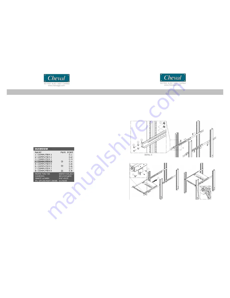
Please follow these simple steps to install the  17” LCD drawer into a server rack:

1. Insert cage nut from rear side of Vertical mounting channel two pieces at four corner. 
2. Adjust the sliding rack mount brackets to match the depth of your server cabinet. Fix 
both brackets at a desired height to the server cabinet rails with two of M6x16 mm 
screw at each mounting point. We recommend to install at 24U or 25U height. 

 Note:

 The slider brackets are extend-able to a rack depth of 22" to 36". 

2. Install hangers to both sides of front-end bracket. Gently slide the 17” LCD drawer 
into the fixed brackets of the rack rail assembly. See step (1) – (3)  in picture below.

3. Fasten the front-end bracket screws. Your 17” LCD drawer is now ready for use; 
locate the handle, slide out the console and flip the LCD cover.
( Note: The front-end bracket screws must be fastened to properly secure the 17” LCD 
drawer to the server rack. )

CV17116-C5                                                                                                                                                                                                CV17116-C5

23

8

Summary of Contents for CV17116-C5

Page 1: ...iagrams p6 Installation p7 Panel Controls and Functions p9 Single MULTIPLE Switch Installation p14 OPERATION p16 Hot Key Operation PORT IDENTIFICATI ON p18 Hot key configuration P20 Hot Key summary P2...

Page 2: ...anagement tool for consolidated server access and control FCC CERTIFICATIONS This equipment has been tested and found to comply with the limits for a Class B digital device pursuant to Part 15 of the...

Page 3: ...llow you to use designated key commands to switch computers Control multiple computers using a simple hot key sequence from your keyboard Manual Port Selectors Push button selectors allow for convenie...

Page 4: ...enable your KVM switch to maintain consistent compatibility with the latest devices and computers Firmware upgrades are free for the life of your CV17116 C5 s integrated CAT 5 KVM switch Refer to the...

Page 5: ...S Item Qty CV17116 C5 1 Power Cord 1 Power Adapter 1 Bracket 2 User Manual 1 Cable Tie 1 Console Cable VGA PS 2 keyboard and mouse 1 Power Adapter External Module 1 Installation hardware kit 1 Please...

Page 6: ...uage Recall Exit Port Selection OSD Hot Key Push button Computer Port Connector RJ 45 Computer Connections Direct 16 via optional Hamster CAT5 dongle one unit required per PC Computer Connections Dais...

Page 7: ...s Page Up Page Down to access the required BANK 3 Move the highlight bar to select a connected computer designated by the power symbol and press ENTER Note This series is designed for 15 levels of dai...

Page 8: ...inch rack systems The sliding brackets feature adjustable positions for rack depths of 22 36 inches Important Information Installing and or removing the Switch module and chassis improperly could void...

Page 9: ...ist of connected computers controls and function keys as well as symbols that refer to the status of each computer HARDWARE INSTALLATION Please follow these simple steps to install the 17 LCD drawer i...

Page 10: ...temp Image Setting settings for clock phase gamma and sharpness Position settings for horizontal and vertical positions OSD Menu settings for OSD positions and OSD display timer Language settings for...

Page 11: ...confirm and exit back to RGB sub menu and press MENU to exit back to the Color sub menu Then please skip to step 6 Color Temp adjusts LCD Color Temp level 9300K Default Color Temp 6500K Default Color...

Page 12: ...vertical level 0 58 Back returns to the main OSD menu 2 Press the SEL button to enter confirm selection 3 Use the and buttons to adjust the values 4 Press the SEL button to execute the settings in the...

Page 13: ...lt setting Factory Mode accesses factory setting mode Back returns to the main OSD menu 2 Press the MENU button to enter confirm selection 3 Use the and buttons to adjust the values 4 Press the SEL bu...

Page 14: ...connect to the Master switch has a BANK ID of 0 The decimal point denotes the Master switch If for example a user selects BANK 2 as the new Master Switch then the BANK ID displays 2 Note a BANK ID suc...

Page 15: ...computers can be added or removed without shutting down the Switch When hot plugging console ports keyboard monitor and mouse if you experience a problem after removing and adding a new mouse perform...

Page 16: ...pt that only one USB port is needed for both USB keyboard and USB mouse Connecting the Power Supply 1 Connect the supplied power cord to the CV17116 C5 s power jack and plug the other end of the power...

Reviews: