Cheval CV17116-C5 Manual Download Page 8

INSTALLATION

Where to Place the Switch

The enclosure of the CV17116-C5 Switch is designed for standalone or rack-mount 
configuration. The Switch is natively rack-mountable in a standard 1U (19”)
server rack. Rack-mount hardware is included with your switch for a sturdy
rack installation.

Cautions and Warnings

Avoid placing cables near machines that create electrical noise such as fluorescent
 lighting, air conditioning equipment, etc.

Important Information

 Before you begin, make sure that power to all the computers you will

be connecting has been powered off.

To prevent damage to your installation due to ground potential
difference, make sure that all computers on the installation are properly
grounded. Failure to follow these instructions can result in damage to
computers and / or the Switch.

Installing the Switch into a Server Rack

Unlike other traditional rack mounted LCD KVM units the CV17116-C5 requires
only one person for installation. The CV17116-C5 includes 2 adjustable sliding
rack mount brackets for installation in 19-inch rack systems. The sliding
brackets feature adjustable positions for rack depths of 22-36 inches.

Important Information

  Installing and or removing the Switch (module and chassis)

improperly could void your warranty. If you are uncertain what to do
please contact our technical support.

Navigation

Use the following to navigate through the OSD menu:

To escape from the OSD menu or sub-menu, press the [Esc] key.

To move up and down through the screen list use the Up / Down arrows.

Move the highlight bar to the desired location and press [Enter] to activate a Port

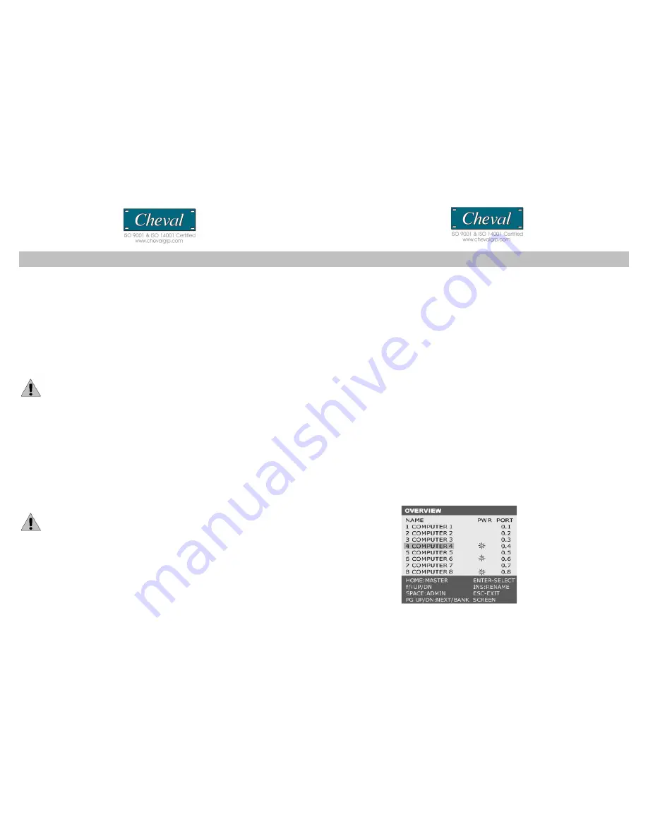
OSD Main Menu Functions

This section provides details on the use of the following OSD functions;
HOME-MASTER, UP/DOWN , SPACE-ADMIN , ENTER, INS and ESC. From the main 
OSD mode, the following OSD functions can be accessed:

HOME-MASTER

To return the KVM focus to the Master switch’s first active port press “Home” from the 
keyboard.

UP / DOWN

To select any computer at the same KVM level, move the highlight bar using the 

↑/↓ 

arrow keys and press [Enter].

(Pg UP/Down)

To scroll through the Previous/Next BANK screen list.

(INS): RENAME

Press the “Insert” key to name each computer by port (up to 15 characters).

(ENTER)

To confirm a selection and save the content input, press [ENTER].

CV17116-C5                                                                                                                                                                                                CV17116-C5

7

24

Summary of Contents for CV17116-C5

Page 1: ...iagrams p6 Installation p7 Panel Controls and Functions p9 Single MULTIPLE Switch Installation p14 OPERATION p16 Hot Key Operation PORT IDENTIFICATI ON p18 Hot key configuration P20 Hot Key summary P2...

Page 2: ...anagement tool for consolidated server access and control FCC CERTIFICATIONS This equipment has been tested and found to comply with the limits for a Class B digital device pursuant to Part 15 of the...

Page 3: ...llow you to use designated key commands to switch computers Control multiple computers using a simple hot key sequence from your keyboard Manual Port Selectors Push button selectors allow for convenie...

Page 4: ...enable your KVM switch to maintain consistent compatibility with the latest devices and computers Firmware upgrades are free for the life of your CV17116 C5 s integrated CAT 5 KVM switch Refer to the...

Page 5: ...S Item Qty CV17116 C5 1 Power Cord 1 Power Adapter 1 Bracket 2 User Manual 1 Cable Tie 1 Console Cable VGA PS 2 keyboard and mouse 1 Power Adapter External Module 1 Installation hardware kit 1 Please...

Page 6: ...uage Recall Exit Port Selection OSD Hot Key Push button Computer Port Connector RJ 45 Computer Connections Direct 16 via optional Hamster CAT5 dongle one unit required per PC Computer Connections Dais...

Page 7: ...s Page Up Page Down to access the required BANK 3 Move the highlight bar to select a connected computer designated by the power symbol and press ENTER Note This series is designed for 15 levels of dai...

Page 8: ...inch rack systems The sliding brackets feature adjustable positions for rack depths of 22 36 inches Important Information Installing and or removing the Switch module and chassis improperly could void...

Page 9: ...ist of connected computers controls and function keys as well as symbols that refer to the status of each computer HARDWARE INSTALLATION Please follow these simple steps to install the 17 LCD drawer i...

Page 10: ...temp Image Setting settings for clock phase gamma and sharpness Position settings for horizontal and vertical positions OSD Menu settings for OSD positions and OSD display timer Language settings for...

Page 11: ...confirm and exit back to RGB sub menu and press MENU to exit back to the Color sub menu Then please skip to step 6 Color Temp adjusts LCD Color Temp level 9300K Default Color Temp 6500K Default Color...

Page 12: ...vertical level 0 58 Back returns to the main OSD menu 2 Press the SEL button to enter confirm selection 3 Use the and buttons to adjust the values 4 Press the SEL button to execute the settings in the...

Page 13: ...lt setting Factory Mode accesses factory setting mode Back returns to the main OSD menu 2 Press the MENU button to enter confirm selection 3 Use the and buttons to adjust the values 4 Press the SEL bu...

Page 14: ...connect to the Master switch has a BANK ID of 0 The decimal point denotes the Master switch If for example a user selects BANK 2 as the new Master Switch then the BANK ID displays 2 Note a BANK ID suc...

Page 15: ...computers can be added or removed without shutting down the Switch When hot plugging console ports keyboard monitor and mouse if you experience a problem after removing and adding a new mouse perform...

Page 16: ...pt that only one USB port is needed for both USB keyboard and USB mouse Connecting the Power Supply 1 Connect the supplied power cord to the CV17116 C5 s power jack and plug the other end of the power...

Reviews: