Chery QQ Service Manual Download Page 53


Chery QQ Service Manual


Mechanical Part of SQR 472Engine


52


Remarks:  In  the  above  tables,  the  capital  letter  and  suffix  following  the  sizes  (For  example,  H

7

  of 

φ

28H

7

)  mean  the 

process precision, which are unconcerned with the maintenance and may be ignored in the course of maintenance. 
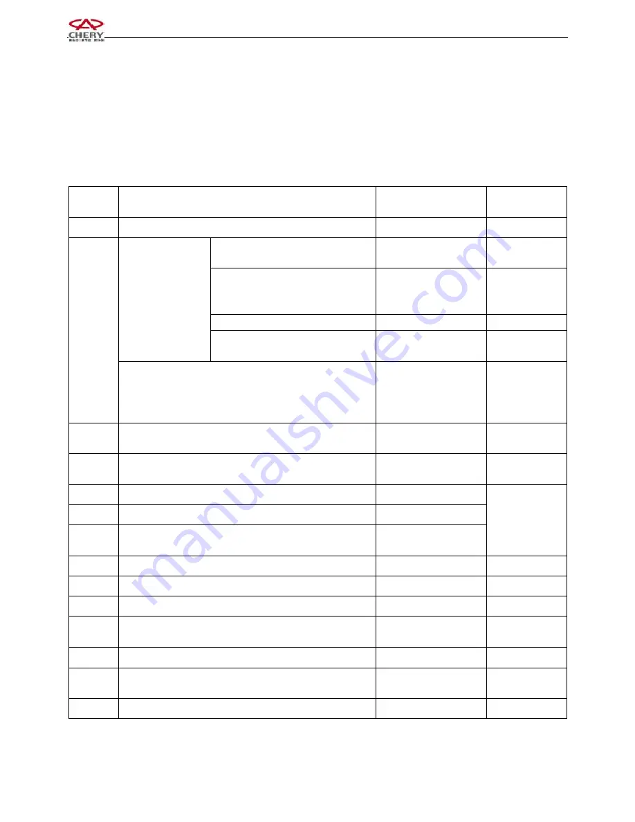
Chapter 4.  Table 

of 

Measurement 

Parameters 

of 

SQR472 

EngineSQR472 


No. 

Measuring Items 

Acceptance value

Remark 

1


Axial clearance of crankshaft


0.089-0.211mm


Assemble the crankshaft and tighten the 

main bearing cap bolt


1 Nm


Mount  the  piston  connecting  rod 

assembly  and  tighten  the  connecting 

rod bolt


5.5Nm


6Nm 


Torque of crankshaft 

when rotating at 

uniform speed


Installing timing belt and spark plug


26 Nm


2


Mount  the  valve,  spring  and  camshaft  (excluding  timing  belt 

and  spark  plug)  on  the  cyllinder  head,  tighten  the  camshaft 

bolt,  and  then  measure  the  torque  of  the  camshaft  rotating  at 

uniform speed


32 Nm


3


Distance between the outer edge of steel ball and the front end 

of camshaft


5.65

±

0.5mm


4


Distance between the outer edge of steel ball and the rear end 

of camshaft


8.65

±

0.5mm


5


Axial clearance of intake camshaft


0.10~0.179


6


Axial clearance of exhaust camshaft 

0.10~0.253


7


Jumping  amount  of  installation  surface  of  flywheel  wearing 

piece 

0.10mm

max


8


Protrusion height of crankshaft woodruff key 

2

2.20mm


9


Intake valve clearance


0.18

±

0.05mm


10


Exhaust valve clearance


0.25

±

0.05mm


11


Tension of timing belt (When the middle part of the rigth side 

is pressed down for 4-5mm


200

280N.m


12


Compression pressure of cylinder


10~14bar


13


Tension  of  generator  belt 

When  the  part  between  the 

generator and water pump is pressed down for 4-5mm


98N.m


14


Refilling amount of engine oil (including filter)


3.5 Liter


Summary of Contents for QQ

Page 1: ...Chery QQ Service Manual Mechanical Part of SQR 472Engine 1 SQR 472 Engine Service Manual for Mechanical Part After sales Department of Chery Automobile Sales Co Ltd...

Page 2: ...2 Disassembly 23 3 Routine Inspection 23 4 Water Pump 29 1 Structure Diagram 29 2 Disassembly 29 3 Cleanup 29 4 Routine Inspection 29 5 Assembly 29 5 Oil Pump 29 1 Structure Diagram 30 2 Disassembly 3...

Page 3: ...n Fit Clearance for SQR472 Engine 55 Chapter 4 Table of Measurement Parameters of SQR472 Engine 59 Chapter 5 Table of Main Fitting Torque for SQR472 Engine 61 Chapter 6 Positions on SQR472 Engine to b...

Page 4: ...nents and installation status are set forth at the beginning of each chapter or section 2 The number in the figure refers to the disassembly sequence of each component The components which may not be...

Page 5: ...on to the operation description It records the operation descriptions of cases about person accident 2 Meaning of Marks and Abbreviations Mark Original Words Intepretation RH Right Hand Right Hand LH...

Page 6: ...ssembly and assembly of engine Clamp hole wrench for camshaft timing gears Disassembly of camshaft timing gears Spring bushing puller Assembly of camshaft Oil seal Valve keeper remove tool Auxiliary t...

Page 7: ...l seal Crankshaft pulley holding tool Disassembly and assembly of crankshaft pulley Wrench Disassembly and assembly of crankshaft driven gear Replace valve clearance adjustment gasket Water pump pulle...

Page 8: ...e or assemble the engine with roll over stand Disassemble or assemble the engine parts on the roll over stand 1 Timing Belt 1 Structure Diagram Water pump pulley Timing shroud Timing belt Torsional da...

Page 9: ...tool Torque 25 1 5 N m 2 2 Disassembly of Timing Belt Cover Torque 6 1N m 2 3 Disassembly of torsional damper Use special tools to prevent the gear ring from rotating When disassembling the fixing bo...

Page 10: ...ver 2 5 2 Screw off the bolt of tension pulley and remove the tension pulley 2 6 Disassembly of timing belt Notice Do not use sharp tools like screwdriver during disassembly of belt Notice Pay attenti...

Page 11: ...ly The water pump leaks water out and requires continuing infusion If the belt is spotted with much oil stains and the rubber may be damaged due to expansion you should replace the belt Timing belt mo...

Page 12: ...th bolts The tightening torque for the bolts is 100 5Nm Make sure that the clashing mark of crankshaft timing pulley aligns with the mark of oil pump 3 3 Install the tension pulley After adjust the te...

Page 13: ...deflection can not reach the standard it is necessary to adjust the fixing bolt of tension pulley mentioned above Tighten the fixing bolt of the tension pulley with the torque as specified The tighten...

Page 14: ...nt the sealing strips at the positions as indicated in the right figure The sealing strips at the position 1 and 2 should be mounted before the assembly of the cylinder head assembly and the sealing s...

Page 15: ...2 Cylinder head cover gasket 3 Camshaft timing belt 4 Camshaft cover 5 Blanking cover 6 Camshaft bearing cap 7 Exhaust camshaft assembly 8 Intake camshaft assembly 9 Camshaft oil seal 10 Axial spring...

Page 16: ...ove the camshaft timing gear with special tool Notice The special tool should be made as indicated in the right figure Use the special tool to prevent the camshaft from rotating 2 3 Remove the camshaf...

Page 17: ...erate as indicated in the right figure Clamp the camshaft and plug the pins of special tool into the hole on gear rotate the gear to keep the meshing of driven gear and driving gear and then remove th...

Page 18: ...Confirm the mark forwards on the bearing cap as well as the axle number and then tighten the bolts 3 Measure the clearance of engaging tooth of the intake camshaft with dia indicator Notice Measure a...

Page 19: ...bolts M5 0 8 Notice Don t damage the journal adjust the operation 3 3 Assembly of camshaft Notice Pay attention to the axial clearance of the camshaft 3 3 1 Spread grease on the gear of camshaft and t...

Page 20: ...ed in the right figure After being pressed the blanking cover should be 1 1mm higher than the surface of thecylinder head 3 7 Spread the edge of the camshaft oil seal with oil and press it into the cy...

Page 21: ...s indicated in the right figure and with the specified torque Torque 6 1N m 4 Inspection of valve 4 1 Standard valve clearance IN 0 18 0 05 Valve clearance EX 0 25 0 05 4 2 Make sure that the timing m...

Page 22: ...head of the cylinder which exceeds the standard value faces upwards and the opening of the valve tappet face inwards 4 4 2 Rotate the crankshaft and press down the valve tappet with the crown head of...

Page 23: ...44 2 66 2 24 2 46 2 68 2 26 2 48 2 70 2 28 2 50 2 72 2 30 2 52 2 74 2 36 2 58 2 80 2 32 2 54 2 76 2 38 2 6 4 4 3 4 Adjust the valve clearance with selected adjustment gasket Notice Install the adjustm...

Page 24: ...er cushion 5 Adjustment gasket 6 Valve tappet 7 Valve spring retainer 8 Valve spring seat 9 Valve Spring 10 Intake valve 11 Exhaust valve 12 Valve oil seal 13 Valve seat 14 Valve guide 2 Disassembly 2...

Page 25: ...eat valve spring intake valve and exhaust Valve etc with special tools 2 6 Disassembly of valve oil seal and valve spring gasket 2 7 Cleanup 2 7 1 Clean the carbon dust on the valve 2 7 2 Clean the bo...

Page 26: ...eter of valve guide with dial gauge the outer diameter of valve stem with micrometer caliper 3 3 2 2 Figure out the difference of measured values and the clearance If the clearance is beyond the speci...

Page 27: ...unt the new valve guide with special tool at the place as can be seen from the right picture Notice strike the conduit slowly to the position in the cylinder head do not strike too far and be careful...

Page 28: ...rted position with inner 70and outer 30 3 3 4 6 Prepare for polishing of valve seal 3 4 Assembly of cylinder head 3 4 1 Cylinder head Pay attention to the following for installing the other auxiliary...

Page 29: ...of intake valve and exhaust valve 3 4 3 2 1 Assembly of valve spring Notice The painting is used for recognizing the different suppliers so the same engine should use the valve spring with same painti...

Page 30: ...ndicated in the right figure for 3 times till the torque reaches the specified value The tightening torque for each time is set forth as follows First time 30 2Nm second time 50 3Nm third time 70 3 5N...

Page 31: ...usable 2 2 Screw off 3 bolts and disassemble water pump body 2 3 Disassembly of dust seal 3 Cleanup 3 1 Clean water pump joint surface 4 Routine Inspection 4 1 Check if it is deformed 4 2 Rotate it wi...

Page 32: ...collector spacer nonreusable Oil pump Oil pump spacer nonreusable Rear oil seal bracket 2 Disassembly 2 1 Screw off the bolts and nuts and then remove the oil pan from the cylinder body with special...

Page 33: ...ce The oil collector gasket is nonreusable 2 3 Remove the engine oil pump assembly and the engine oil pump gasket 2 4 Remove the rear oil seal bracket 3 Cleanup 3 1 Remove the old cushion from the oil...

Page 34: ...ter Pin Oil Drain Valve Spring base Oil Drain Valve Spring Slide Block Crankshaft Front Oil Seal Engine Oil Pump Housing 4 2 Disassembly 4 2 1 O ring Notice The O ring is nonreusable 4 2 2 Remove the...

Page 35: ...and oil pressure relief valve etc 4 2 6 Remove the front crankshaft oil seal Notice The oil seal removed may not be reused 4 3 Routine Inspection 4 3 1 Inspect the engine oil pump for clearance 4 3 1...

Page 36: ...e oil pressure relief valve 4 4 Installation 4 4 1 After the lip of the new oil seal for front crankshaft is spread with engine oil fix it with a special tool Notice Use new oil seal The oil seal shou...

Page 37: ...4 4 3 When the outer gear or inner gear is put into the engine oil pump its mark should be seen 4 4 4 The new weather strip should be fixed in the groove of oil pump cover 5 Disassembly of Oil Seal 5...

Page 38: ...il seal with special tool as indicated in the right figure 6 Assembly 6 1 Assembly of the oil seal seat Spread sealant over the oil seal seat as shown in the right figure Grease Loctite 5699 Notice Sp...

Page 39: ...pan with the cylinder 6 4 2 Spread sealant then assemble it Grease Loctite 5699 Notice The sealing line should be unbroken with its diameter being 3 4mm Assembly should take place fifteen minutes aft...

Page 40: ...Structure Diagram Connecting rod cover Connecting rod bushing Piston connecting rod assembly Main bearing cap Crankshaft Crankshaft bearing bushing Thrust plate Cylinder body First ring Second ring St...

Page 41: ...ting rod bushing for its radial clearance 2 2 1 Remove the bushing cap Notice The components of each cylinder shall be placed in order 2 2 2 Clean the bearing bushing and the axle 2 2 3 Conduct radial...

Page 42: ...connecting rod bearing bushing 2 2 7 Put vinyl resin protecting jacket on the threaded part of the connecting rod bolt so as to prevent the bolts from scraping the cylinder hole and the crannkshaft co...

Page 43: ...m Notice After tightening the bolts the rotating torque of the crankshaft should be less than 1Nm The torque of crankshaft without piston connecting rod 2 4 4 Remove the bearing cap and measure the ma...

Page 44: ...As indicated in the right figure disassemble the piston which is at the state mentioned above with special tools Remove the piston pin with special tool and then remove the piston and the connecting r...

Page 45: ...b Cylindric degree A a or Reference Standard diameter of cylinder 72 00 72 01mm 4 2 Piston 4 2 1 Inspect the piston pin hole for its clearance Measure the piston pin at several positions with a microm...

Page 46: ...e ring gloove 4 2 5 1 Measure around the ring gloove with a piston ring and a feeler gauge Standard value mm Limit mm First ring 0 03 0 06 0 12 Second ring 0 03 0 06 0 11 4 2 6 Inspect the end clearan...

Page 47: ...rankshaft 4 3 1 Inspect the proper alignment of the main axle diameter 4 3 1 1 Measure the proper alignment with a dial gauge if the proper alignment is beyond the limit replace the crankshaft Limit 0...

Page 48: ...hine Notice When pressing in the piston pin make sure the fitting direction is correct When the piston pin is pressed into the piston the small end of the connecting rod should be heated to 300 and th...

Page 49: ...t the side with oil gloove crankshaft shank face outwards Notice Spread the side of oil glove with oil 5 3 4 Fix the crankshaft bearing bushing lower piece in the bearing cap the bearing bushing shoul...

Page 50: ...should be spread with engine oil 5 4 4 Confirm the mark forwards of the piston and strike it into the cylinder body with the piston ring striking tool Notice The cylinder number of the piston and conn...

Page 51: ...Crankshaft Connecting Rod Bearing Name of Component Size and Tolerance Clearance or Value of Interferenc Remark Crankshaft connecting rod journal 37h6 0 016 0 Bearing bushing 1 5 0 006 0 Bore of conne...

Page 52: ...f6 005 0 014 0 Clearance 0 005 0 029 8 Radial Clearance of Camshaft Bearing Name of Component Size and Tolerance Clearance or Value of Interferenc Remark Cylinder Head 26H7 021 0 0 1st bearing cap Ca...

Page 53: ...and spark plug on the cyllinder head tighten the camshaft bolt and then measure the torque of the camshaft rotating at uniform speed 32 Nm 3 Distance between the outer edge of steel ball and the fron...

Page 54: ...ug M12 1 45 3 9 Oil pan bolt M6 19 6 1 10 Bolt connecting exhaust camshaft with flange hexagonal M6 4 6 1 11 Exhaust camshaft locking nut M40X1 5 L 1 100 5 12 Cylinder head bolt M10X1 25 10 70 3 5 13...

Page 55: ...1 100 5 32 Water pump pulley bolt M6 4 6 1 33 Water temperature sensor M12X1 5 1 15 1 5 34 Oil pressure switch 1 30 2 35 Spark plug M14X1 25 4 20 1 36 Fixing Bolt of spark plug cover board M6 8 2 5 0...

Page 56: ...6 Inner wall of cylinder hole 7 Crankshaft main neck 8 Connecting rod shaft neck 9 Upper lower main bearing bushing inside 10 Upper lower connecting rod bearing bushing inside 11 Crankshaft thrust pla...

Page 57: ...ite 5699 3 4 mm 5 Joint surface of camshaft cover Loctite 5699 3 4 mm 6 Sealing surface of the bowl shaped plug of cylinder head Loctite 11747 Spread uniformly 7 Flywheel bolt Loctite 204 0 125 ml 6 P...

Page 58: ......

Page 59: ......

Page 60: ...01 2 1 0 1 0...

Page 61: ...3 4 5 6 7 7 2 8 6 6 9 4 3...

Page 62: ...4 2 6 4 4 4 9 9 6 4 2 6 9 4 6 9 6 9 6 7 9 8 8 8 7 6 6...

Page 63: ...8 4 6 7 4 8 9 5 8 8 2 8 8 2 8 A A 8...

Page 64: ...01 2 012 0 40 7 03 0145406 768 4694 2 4 9 8 2 4 4657 2 211 2 12610 8 3 9 6 B 8 4 4 4657 2 523 2 75 2 8 2 C D 8...

Page 65: ...7 7 5E 7 5 847 60141 7 6 9 D 7 6 9 7 6 4 8 8 F 3 3 3 3 3 8...

Page 66: ...1 D 4 0 0 02 012 7 8 7 2 4 7 03 0145406 768 4694 2 4 9 8 7 8 7 7 7 7 7 C7 7 5 847 60141 7 9 9 7 6 A 6 1123 D 4 8...

Page 67: ...0 D 4 0 0 2 012D 7 6 03 0145406 768 4694 2 2 4 7 4 7 7 7 5 847 60141 7 6 6 8 4 4 9 4345 8757 G H5E 6157 605492 G 05492 461 0I 5E 0I 0 0 5E E...

Page 68: ...7...

Page 69: ...D 4 00 0 02 012D 7 03 0145406 768 4694 2D 5 3 7 9 7 9 7 9 7 5 847 60141 7 D 8 5 5 461 8 3 7 5...

Page 70: ...7 1123 605492 0G 8 9...

Page 71: ...D 4 0 02 012 9 9 7 9 4 9 03 0145406 768 4694 2D 9 9 00I 9 9 9 9 9 9 9 7 6 9 4 8C K L C 9 0 40 1 4 0 8 8 7 9 9 8 9 6 A2 B0465 C71 D0 461 2 2 2 2 9 A...

Page 72: ...7 5 847 60141 7 D 3 6 8 9 6 7 1123 605492 9 04 0 9 M 9 9 7 7 9...

Page 73: ...4 D 8 9 0 4 1 8 9 7...

Page 74: ...D 4 0 0 02 012 7 7 8 7 6 7 A8 7 7 N 7 4 4 0I 4 0I 8 03 0145406D 8 7 1123 M 9 7 4 7...

Page 75: ...D 7 1 8 0 7 8 8 1 9 7 0 8 7 9 3O 7 1 7 3 4 7 O 3 0 5 7 4 A 7 4 A 1 0 7 A 7 7 8C A 7 7 1 A 7 9 0 7 7 7 O 1 8 O 8 O 0 8 4 7 A 8 1 7 7 0 7 O 3 5 7 7 7 7 1 7 7 0 7 5 7 46 2D4645406 68 0465 E52 40...

Page 76: ...1 D 4 0 02 012 6 03 0145406 768 4694 2D M 2 9 7 0 K2 9 8 4 4 9 0 9 4 054921 9 M 7 M 461 8 8 POQ P4Q A A...

Page 77: ...0 D 4 0 02 012 8 6 7 6 03 0145406 768 4694 2 8 7 6 AK 6 9 M 0 6 1123 6054921 8 6 6 M 4 4 3 6 6 JJ 6 9 05492 9 6 M 6 7 5 847 60141 6 6 6 9 4 4 4 8 6 6 461 6 7 D M 6 6 F A...

Page 78: ...F 3 D 4 0 0 02 695406 8 3 7 6 6 6 6 7 2 03 0145406 768 4694 2 8 4 8 0I 0 0 0 0 0 0 00 4 0 0 R 00K 9 0 0 R K N 7 5 847 6014 7 8 8 461 1 7 0 7 7 7 A D...

Page 79: ...M 6 05492D...

Page 80: ...D 4 0 002 695406D 8 9 682 268265 4 645406 8 4 9 7 03 0145406 768 4694 2D 8 7 9 7 5 847 60141 7 7 9 3 4 9 437 G46846 0 E 290687 G46846 E 8 461 4 D POQ P4Q 7...

Page 81: ...012 7 2 9 9 03 0145406 768 4694 2 7 8 7 7 5 847 60141 7 4 4 4 E 0I 2 4 461 8 7 A...

Page 82: ...012 9 6 6 4 03 0145406 4 3 4 6 4 1123 2H 4 23265 7 5 847 60141 4 D 05492 6 4 M 8...

Page 83: ...7 7 7 4 9 4 4 2 7 A8 A 4 P Q P Q 9 2 9 7 P 4 Q P 4 9 Q P Q P 9 Q M 4 4 7 9 7 9 8 9 8 000 7 9 6 7 A 7 4 9 M...

Page 84: ...1 4 9 4 9 D P Q 7 9 A 9 3 9 7 2 9...

Page 85: ...8 A P Q 9 S 9 8 S A A 7 S A 7 2 2 A 7 8...

Page 86: ...1 A P Q 9 S 9 2 2 9 2 2 E A A A 8 2 42 2 O2 A 7 A 7 2 2 2 A 7...

Page 87: ...0 5 A 9 9 8 3 E A 9 5 8 3 A 9 A 7 0 8 3 A 7 5...

Page 88: ...8 8 8 A P Q 9 2 2 9 A 7 0 2 2 2 9 9 A 7 7 8 2 2 0 2 A 7 8...

Page 89: ...9 A P Q 9 9 9 2 O2 2 42 A 7 9 2 2 E ET 9 A A 9 9 A 2 2 2 7 2 9 9 9 9 9 2 O2 2 42 0 0 1 A A 7 2 12 7 2 2 A 7 9 A...

Page 90: ...8 8 A P Q 9 9 2 2 A 7 2 2 2 A A 7 2 2 2 A 7 8...

Page 91: ...E A P Q 9 9 2 O2 2 42 A 7 2 2 2 A A 7 2 2 A 7...

Page 92: ...6 A 9 6 2 O2 9 A S P Q 9 A 6 6 2 O2 9 A A 7 7 2 6 6 9 A S 9 2 2 6 4 E 0 6 c E A 6 A 6 6 8 6 6 8 6 A 7 A 6 F...

Page 93: ...A 9 S 9 6 6 S 9 6 9 00 S A 7 2 2 0E A S A 2 9 A S A 7 7 2 A 7 A...

Page 94: ...A P Q 9 S 9 S 9 A S A 7 0 7 6 A 7 S A 9 9 S A 2 9 A...

Page 95: ...8 A 9 S 9 6 8 0 0 A S 9 8 A S A 9 7 1 0 6 S A 8...

Page 96: ...1 2 2 2 2 2 4 2 4 2 2 4 4 12 2 7 9 2 2 2 2 9 9 8 D 8 9 8...

Page 97: ...0 A S 9 4 A S 9 P Q 04 A S 9 A S 9 A S A 9 S 6 9 S 9 A...

Page 98: ...A S P Q 9 S 4 0 9 S 9 TC A S A 9 S A 9 9 S 9 A S 9 S 9 P Q S 9 1 0 0 S 0 6 6 6 8 6 6 6 9 S 9 6 A 6 S A S 9 0 S 9 6 S A...

Page 99: ...A S A 6 2 A S 9 7 7 7 7 A S A 9 S A 1 6 9 S 9 0 A S A 7...

Page 100: ...A S P Q 9 S 9 2 0 0 1 S 9 00 0 A S A 2 0 2 9 S A 6 6 9 S 6 9 S 9 7 7 7 7 A S A A 7 S 9 1 6 A S 9 0 A S 9 A S A A 7...

Page 101: ......

Page 102: ...A S P Q 9 S 9 A S 9 8 S A S 9 0 0 1 S 6 6 6 9 S 9 6 A 6 S A S 9 1 0 S 9 0...

Page 103: ...S A 2 A 6 S A 6 A S A 6 A S 9 6 I A S 9 P Q D 1 0 S 9 A 7 I 8 6 S 9 S A 6 9 S A 7 1 A...

Page 104: ...A S P Q 9 S 9 E 7 0 2 A S 9 7 D 1 0 S 9 A S 9 8 4 4 S 9 S 9 6 I A S 9 2 0 S 1 6 6 6 9 0 6 S 9...

Page 105: ...A 6 S S 9 0 S 9 S A 2 A 6 S A 6 A S A 6 2 A S 9 S A 9 S A 1 6 A 7...

Page 106: ...1 S P Q 9 S A 6 9 S 7 7 2 1 0 2 1 9 S A 2 9 S 9 6 6 S 9 M A S A 9 S 9 A S 9 1 0 0 S 0 6 6 6 9 6 S 9...

Page 107: ...0 A 6 S S 9 0 S 9 S A 2 A 6 S A 6 A S A 6 2 A S 6 9 S 9 1 A 8 9 9 S 0 9 S 9...

Page 108: ...S P Q 9 S 9 A S 9 A S 9 7 7 S 9 6 A S 9 A...

Page 109: ...S P Q 9 S 9 P Q 7 7 0 2 2 2 9 2 7 1 0 2 A S 9 A S 9 S 9 0 0 1 S 6 6 6 9 S A 6 A 6 S S 9 1 0 S 9 0 2 S A...

Page 110: ...2 A 6 S A 6 A S A 6 2 A S A 9 S 9 S 9 M A S A 9 S A 7 1 A...

Page 111: ...S P Q 9 S 9 7 7 0 8 2 S 9 A S 9 P Q 7 1 0 2 S A 6 9 S A 7 A...

Page 112: ...S P Q 9 S 9 A S 9 A 4 4 S A 9 S 9 P Q 7 7 2 0 2 2 9 2 2 2 7 1 0 2 A S 9 A 8 6 S 6 9 S 9 S 9 1 6 6 6 6 S 9 0 M A S A...

Page 113: ...9 S A 7 A S P Q 9 S 8 6 9 S A 9 S 9 A S A 9 S A A 9 S A 9 S A 6 9 S A 1 A 9 S 9 0 6 A S A 7 A...

Page 114: ...S P Q 9 S 9 A S 9 A 9 S 9 A 4 4 S 9 A 8 6 S 9 0 0 0 S 1 6 6 6 9 S 9 6 A 6 S A 1 S 9 0 0 S 9 S A 2 A 6 S A 6 A S A 6 2 A S 9 P Q 7 7 2 2 2 A S A 7 A...

Page 115: ...S P Q 9 S 9 A S 9 A A S 9 A S 9 7 7 2 2 2 A S 9 A 8 6 S 9 0 0 00 S 0 6 6 6 9 S 9 1 6 A 6 S 0 S 9 0 S 9 S A 2 A 6 S A 6 A S A 6 2 A S A 9 4 6 A 7...

Page 116: ...1 S A 4 9 S 9 A S P Q 9 S 9 A 8 6 S 9 P Q 7 7 2 0 2 2 9 2 2 2 7 1 0 2 A S 9 A S 9 0 00 S 0 6 6 6 9 S 9 1 6 A 6 S 0 S 9 0 S 9...

Page 117: ...0 S A A 6 S A 6 A S A 6 A S 9 A S 9 8 6 S A 7...

Page 118: ...S 9 4 UV 4 S A 4 A 9 S 9 7 7 0 8 2 WX A 9 S A 7 2 A 7...

Page 119: ...2 A 4 4 0 2 A 4 4 6 4 2 8 4 4 2 4 D 8 4 A S 4 6 8 8 6 6 2 M 9 2...

Page 120: ...00 6732 695406 00 6732D 695406D 00 6732D 695406D 6...

Page 121: ...00 6732D 695406D A C 00 6732D 6 695406D 6 00 6732D 695406D 00 6732D 695406...

Page 122: ......

Page 123: ...0 1 2 3 2 2 4 5...

Page 124: ...6 1 7 8 9 9 6...

Page 125: ...2 5 1...

Page 126: ...f torque 14 Section 6 Repair Materials Needed 14 Chapter 2 Transaxle 16 Section 1 Brief Technology Introduction of DABS10 4 Transaxle 16 Section 2 Transaxle Maintenance on Car 23 Section 3 Transaxle D...

Page 127: ...s in the leading position 3 DABS10 4 Gearbox Usage Maintenance Manual Book is edited at the request of our customers It describes in details each parts of the gearbox and the relations between every p...

Page 128: ...bearing draws back the edges of diaphragm spring is beginning to drive the platen against the flywheel This is the clutch jointing state Step on the clutch pedal to move release bearing forward diaphr...

Page 129: ...he clutch vibrate The clutch disc has been frayed as clean as whistle The clutch disc have greasy dirt The Release bearing glides badly on the Spacer The clutch disc shakes or the clutch disc contacts...

Page 130: ...ate of the clutch is normal under the circumstance that the engine is running 3 Clutch Switch Attention This switch is applicable to the vehicles with catalyst Adjust 1 Pull the parking brake handle p...

Page 131: ...on the fixing surface of cable and fix the cable on the front wainscot with two bolts Switch lock nut Torque 4 7 0 4 0 7 3 0 5 0 Tighten connect nut turn the connect nut to adjust free play specifica...

Page 132: ...l up the input shaft input shaft bearing with special tools Check the input shaft bearing Check if the input shaft bearing runs smoothly If appears abnormity please replace the bearing Clutch disc ass...

Page 133: ...int on it if necessary please repair or replace Installation Attention Before assembling check the flywheel surface and platens 1 Whether surface is clean and dry 2 Install the flywheel on the cranksh...

Page 134: ...and leave the tap in spacer NO 1 4 Screw a connection hose with tap and then connect the hose with the oil seal puller strike the spacer NO 1 Check 1 Check if the clutch release bearing turns smoothl...

Page 135: ...lutch cable bracket Pack the clutch separation arm Lubricate the release fork assembly and the input shaft Screw the torque tightly N m Kg m 1b ft Release shaft bolt 10 16 10 1 6 7 5 11 5 Cable bracke...

Page 136: ...icates the fat A 99000 25010 Pulling cable catch connecting pin Release fork spacer and seal Release bearing and release shaft The lithium lubricates the fat The SUZUKI high class lubricates the fat I...

Page 137: ...que 72 N m Contour size 409 392 342 7 mm Angle transaxle 5 Lubricant 18 hyperbolic gear oil Q SH006 1 27 89 II Driven special This transaxle consist of three groups of synchronizer input shaft and out...

Page 138: ...ssembly 6 3rd gear 7 Transaxle case 8 Reverse gear shaft 9 Reverse gear 10 Clutch case 11 Output shaft 12 Transaxle behind case 13 5th driven gear 14 4th driven gear 15 3rd driven gear 16 2nd driven g...

Page 139: ...18 5th snap ring 19 5th synchronizer assembly 20 5th Synchronizer insert 21 Thrust washer 22 Snap ring 23 Reverse gear shaft 24 Reverse gear 25 gasket 26 Output shaft bearing 27 Output shaft 28 1st dr...

Page 140: ...fork assembly 3 Reverse 5th shaft 4 Reverse 5th shift fork shaft 5 3rd 4th shift fork shaft 6 1st 2nd shift fork shaft 7 Select lever shaft 8 Reverse 5th shift cam 9 Reverse 5th Interlock roller 10 C...

Page 141: ...ring and reach the expected joggled state Under the circumstance of the neutral spring on the shift and select lever shaft keep the shift and select lever shaft stay on the neutral The interlock in t...

Page 142: ...elect lever shaft moves to neutral of 3rd 4th the shift restrict bolt cam cannot effect as the Figure 16 3 shift select lever shaft to 5th or reverse shift cam and bolt fixup 1 Shift and select lever...

Page 143: ...ficult to shift Lubricant is not enough The clutch pedal free play is not correct The clutch disc has been broken The clutch pressure plate has been broken The synchronizer has been frayed The gear ha...

Page 144: ...el and if there is any leakage 3 Let out all the used transaxle oil fill 2 1 L synthetic 18 gear oil the oil level is equal with the foot of the filler plug 4 Before installation spread oil on the who...

Page 145: ...the two brackets 5 Remove Ball joint bolt and disjoin the Suspension arm from the steering 1 Steering 2 Ball joint bolt 3 Suspension arm Fig 2 3 6 Insert a big screwdriver into the connection of the...

Page 146: ...hed the right position and the snap ring has been put into the snap ring slot Do not hammer the boot of the drive shaft III VEHICLE SPEED SENSOR Dismantle 1 Disconnect the cathode of the battery 2 Dra...

Page 147: ...pport driven gearbox install the slotted spring pin check if the gear turns smoothly 4 Check if there are some lacuna on the O seal and gearbox Spread some oil on the O seal and then install the drive...

Page 148: ...rvice Manual Transmission System 45 1 Driven gear 2 Slotted spring pin 3 Driven gear box 4 Special tool 5 Special tool 6 O seal ring 7 Gear box snap ring 8 Oil seal 9 Special tool Fig 2 8 Chery Automo...

Page 149: ...eter driven gear Fig 2 10 Installation 1 Check if there is any crack and disfigurement on the surface of the o ring and SPEED SENSOR case spread lubricant on the o ring and Speedometer driven gear ins...

Page 150: ...ransmission System VI Shift and select lever shaft control system 1 Shift handle assembly 2 Shift mechanism assembly 3 Shift cable assembly 4 Bolt 5 Bracket 6 Nut 7 Clip 8 Washer 9 Cotter pin 10 Bolt...

Page 151: ...the 4 pieces of control shift lever retainer bolt Demount the strengthen pole nut beside the transaxle and move the strengthen pole aside In the cab 1 Have shift lever shaft housing disassembly 2 bol...

Page 152: ...vel 1 Shift lever 2 Shift lever assembly 3 Adjust washer 4 Shift lever 5 Snap ring 6 Shift lever 3 Install shift lever assembly and the related parts on the original position When fixing the position...

Page 153: ...et 3 Disconnect the wiring harness and connector 4 Remove the speedometer cable boot and dismantle the speedometer cable 5 Remove the fixing transaxle bolt 6 Remove the 2 starter bolt and starter mean...

Page 154: ...transaxle by transaxle jack 11 From engine retainer bracket disassembly 2 blot 12 First remove the 3 bolt and 2 nut then remove the bracket 13 Down the jack and the transaxle disassembly the bolt bet...

Page 155: ...transaxle drive shaft do not scrape oil seal When put the drive shaft universal coupling on the differential gear do not hammer the universal coupling Clip wiring harness After connecting the clutch...

Page 156: ...4 Hammer the slotted spring pin out Notice It is much easier to magnetize the guide ball 5 Remove the 5th shift fork hub sleeve synchronizer ring and 5th gear with professional tools Caution Be sure...

Page 157: ...hub sleeve Section 4 Maintenance of the transaxle I Disassemble 1 5th gear 1 Loosen 8 bolt remove the rear gear box 2 Remove the snap ring thrust gasket Caution do not distort the snap ring 1 Snap ri...

Page 158: ...Slotted spring pin 3 Snap ring 4 Special tool Fig 3 2 5 Remove the 5th Shift fork 5th synchronizer assembly synchronizer ring 1 5th shift fork 2 5th hub sleeve 3 5th hub 4 5th synchronizer ring Fig 3...

Page 159: ...welded part of the nut 1 5th lock nut 2 Nut 3 Chisel Fig 3 5 8 Remove 5th driven gear 5th gear transmission thrust board 2 Shift and select lever shaft input shaft output shaft 1 Loosen 3 bolt remove...

Page 160: ...cial tool 5 Clip 6 Shift fork bolt 7 Reverse 5th Interlock roller Fig 3 8 5 Screw off the restrict bolt and gasket 6 Remove the backup light switch Notice When removing the shift and select lever shaf...

Page 161: ...into the joint of the two crust otherwise the joint can be damaged 1 Aluminum Hammer 2 Special tool 3 Transmission case Fig 3 11 11 Take apart the transmission assembly from the clutch case lift the t...

Page 162: ...idler gear shaft assembly 3 Reverse idler gear 4 Reverse Shift fork bolt Fig 3 13 15 Use a rubber hammer to hit the end of the input shaft lightly and force it out a little take out the input shaft a...

Page 163: ...y Fig 3 14 3 Clutch case assembly 1 Remove the differential assembly from the clutch case 1 Differential Assembly Fig 3 15 2 Loosen the bolt pull out the speedometer driven gear assembly 1 Clutch case...

Page 164: ...ol Fig 3 17 5 Loosen the bolt pull out the shift head 1 Shift head 2 Shift lever 3 Bolt Fig 3 18 6 Loosen the shift lever bolt and gasket take out the spring and ball 7 Remove the shift lever boot and...

Page 165: ...ht bearing Fig 3 20 2 Use special tools to clip the 4th gear pull it out with the 5th gear spacer left bearing Caution Do not clip the gear head or the 4th gear may be hurt 1 Special tool 2 Input shaf...

Page 166: ...aring 1 Input shaft 2 Synchronizer assembly 3 Synchronizer ring 4 3rd gear Fig 3 23 7 Disassemble the Synchronizer assembly Check and re install 1 Clean up all the parts check if there is anything abn...

Page 167: ...n install the spring according to the Fig 1 Snap ring 2 Synchronizer insert 3 Hub 4 Hub sleeve outer race 5 3rd gear 65 Fig 3 26 Notice Keep right directions of every part Pay more attention to the si...

Page 168: ...l tool Notice Be sure to keep the synchronizer insert of the synchronizer ring and the synchronizer insert of the synchronizer assembly in the right position when installing the synchronizer assembly...

Page 169: ...er to press the left bearing 10 Use special tool to press the 5th gear spacer 1 5th gear spacer 2 Left bearing 3 Special tool Fig 3 30 Notice In order to avoid the 5th gear spacer pressure over do not...

Page 170: ...he driven gear 3rd driven gear with the Spacer together Caution In order to avoid breaking the 2nd driven gear do not clip the gear head 1 Special tool 2 Spacer 3 Output shaft 4 3rd driven gear 5 2nd...

Page 171: ...shaft 2 Hub sleeve outer race 3 1st synchronizer ring 4 1st driven gear 5 Special tool Fig 3 34 Check and re install 1 Clear up all the parts check if there is anything abnormal if necessary change t...

Page 172: ...a Use limit 0 5mm 3 In order to keep lubricate smoothly blow the oil away be sure there is not any backup in the oil way 1 Output shaft 2 Oil way Fig 3 36 4 Install the synchronizer assembly insert 3...

Page 173: ...bearing 1 Output shaft right bearing 2 Output shaft 3 Special tool Fig 3 38 6 Spread lubricant on the needle roller bearing and then install the 1st driven gear and 1st synchronizer ring 1 1st synchro...

Page 174: ...ring and then install the 2nd synchronizer ring and 2nd driven gear 1 1st driven gear 2 Synchronizer assembly 3 Snap ring 4 Needle roller bearing 5 2nd synchronizer ring 6 2nd driven gear 1 Synchroniz...

Page 175: ...l the 4th driven gear 11 Use hammer or special tools to install the left bearing Notice To protect the bearing use the special tools shown in the figure to support the bearing 1 Left bearing 2 4th dri...

Page 176: ...nap ring and component from the select lever shaft 2 Clear up all the parts if necessary please replace the used parts 3 Install according to the reverse process Notice When hammering the slotted spri...

Page 177: ...fork 3rd 4th Shift fork shaft assembly 1 Use the professional tools to remove the 3 pin and component from the select lever shaft assembly 2 Clean up all the parts if necessary please replace the use...

Page 178: ...carefully to determine if replace the parts Clearance a Maintenance Limit 1 0mm 2 Insert the shift lever into the hole of the case check if it works smoothly if there is any retardarce please correct...

Page 179: ...tely install the reverse shift fork ball Install the shift fork Slotted spring pin according to the reverse order 7 Differential Assembly Disassembling 1 Differential ring gear 2 Lock nut 3 Nut 4 Pini...

Page 180: ...bearing 1 Bearing puller 2 Special tool 3 Left bearing Fig 3 51 4 Clip the differential case remove the 8 nut 8 Differential bolt and 4 lock nut 5 Hammer off the slotted spring pin remove the pinion...

Page 181: ...d of the dial indicator on the top of the gear Use 2 screwdrivers to move the gear read the reading on the dial indicator Fig 3 53 Right Side According to the same process above put the end of the dia...

Page 182: ...ool to support bearing drift the lift side bearing and then install the right side bearing according to the step 4 1 Differential right bearing 2 Speedometer driven gear 3 Slotted spring pin 4 Differe...

Page 183: ...of the output shaft 3 Spread lubricant on the shift lever oil seal use hammer and special tools to install the oil seal from the top down 1 Shift lever oil seal 2 Special tool Fig 3 58 4 Install the s...

Page 184: ...pecial tool A Blow hole downward Fig 3 59 6 Install the shift head on the shift lever Torque 31 5 35 5 N m 1 Shift head 2 Shift lever 3 Bolt Fig 3 60 2 Transmission case 1 If remove the oil guide slot...

Page 185: ...nd spread lubricant on the oil seal 1 Differential left oil seal 2 Special tool Fig 3 62 3 Use rubber hammer to knock the output shaft left bearing outer race and fix it 1 Transmissan case 2 Bearing o...

Page 186: ...ssembly 1st 2nd shift fork assembly and 3rd 4th Shift fork assembly and fix them on the clutch case Notice Use hammer to rivet the input shaft right bearing into clutch case Be sure output shaft and d...

Page 187: ...r gasket has been fixed on the reverse gear Be sure that the distance between reverse shift fork free is 1mm 1 Reverse idle gear shaft assembly 2 Clutch case 3 Reverse Shift fork assembly 4 Reverse ge...

Page 188: ...g free length Standard Use Limit Reserve 5th spring Red 33 8 32 7 Spring Green 33 6 32 5 12 Install the shift lever shift fork shaft ball spring bolt Torque 10 16 N m 1 Bolt 2 Gasket 3 Point spring Gr...

Page 189: ...e and the ruler Clearance a adjust gasket 0 08 0 12mm 3 Repeat the above steps choose a suitable adjust gasket and put it on the bearing outer race Notice Use 0 1mm Feeler gauge to determine if the ga...

Page 190: ...8 12 N m 1 Bolt 2 Transmissan case 3 Input shaft 4 Reserve 5th guide shaft 5 Output shaft Fig 3 73 5 Install the 5th hub sleeve 5th clutch hub 5th Synchronizer insert and 5th snap ring Notice Keep the...

Page 191: ...case A Blow hole Fig 3 81 3 Install the select shaft assembly Notice When installing shift select shaft assembly keep the shift head in the middle position to prevent interlock bolt 4 Connect the shi...

Page 192: ...case assembly clip and hanger assembly Screw down the 4 bolt Torque 8 12N m 1 Hang ring assembly 2 Bolt 3 Guide case assembly 4 Special tool 5 Clip 6 Shift Shift fork shaft bolt 7 Reserve 5th Interlo...

Page 193: ...86 Clutch release shaft Round 1 Spacer1 2 Release shaft assembly 3 Release spring 4 Spacer 5 Bolt 6 Nut 7 Clip Disassemble 1 Disassemble the clip loosen the bolt remove the clutch 2 Turn the release...

Page 194: ...tallation 1 Use special tool to drive in the sleeve 1 and spread lubricant 2 Install the release shaft and return spring 1 Spacer1 2 Special tool Fig 3 91 3 Spread lubricant in the spacer2 and fix it...

Page 195: ...Spread lubricant inside the release bearing and on the release shaft install the release bearing 8 Spread a small quantity of lubricant on the end face of the input shaft splined hub 1 Release bearin...

Page 196: ...ork bolt 18 28 Transmission bolt 15 20 Guide case bolt 4 8 12 Restrict bolt 18 28 Shift fork shaft point bolt 3 10 16 Transmission bolt 14 15 22 Transmission baffle bolt 3 8 12 Bracket bolt 18 28 Bear...

Page 197: ...Release shaft Lubricant Lubricant Needle roller bearing Gear Seal glue HZ1213Q 320222 YAP02 92 Clutch case and transmission case surface Transmission case and gear case surface Transmission case and...

Page 198: ...pter 5 Special Tools Snap ring pliers Dial indicator Dial indicator bracket Bearing install tool Bearing install tool Bearing install tool Bearing install tool Slotted spring pin disassembly tool Bear...

Page 199: ...Bearing tool Bearing install tool Oil seal install tool Bearing outer race install tool Slotted spring pin disassembly tool Bearing install tool Bearing install tool Bearing disassembly tool Spacer d...

Page 200: ...QQ Service Manual Transmission System 98 Chery Automobile Co Ltd Bearing install tool Spacer disassembly tool Spacer disassembly tool Handle Puller slide hammer Puller 5th gear lock tool E ring instal...

Page 201: ...fferential 1 Wheel universal joint right 2 Boot 3 Driven shaft 4 Boot 5 Differential universal joint right 6 Differential universal joint left 7 Boot 8 Driven shaft 9 Boot 10 Wheel universal joint lef...

Page 202: ...t splined hub 1 Driven shaft universal joint left 3 Remove the joint from the Suspension arm 4 Remove the ball joint bolt and nut and disconnect the suspension arm from the steering 1 Steering 2 Ball...

Page 203: ...eak the snap ring away from differential universal joint splined hub 2 Disconnect the joint from the suspension arm 3 Remove the ball joint bolt and nut and then disconnect the suspension arm from the...

Page 204: ...he central bearing seat bolt remove the output shaft from differential side gear 3 Disassemble the propeller shaft 1 Remove the differential universal joint boot hoop 1 Boot hoop 2 Move the boot to th...

Page 205: ...and boot 1 Holding Notice The end of wheel universal joint III Installation 1 Installation of propeller shaft 1 Clean the parts except the boot and dry the parts with compressed air 2 Use a piece of c...

Page 206: ...ssion System 104 Chery Automobile Co Ltd 1 Boot 2 Boot hoop 4 Install the holding Caution When installing the holding keep the small diameter towards the shaft end 1 Holding 5 Use special tool A to in...

Page 207: ...ding 7 Put the holding into the bell mouthed and then put the snap ring in the snap ring slot Caution snap ring hatch A can not aim at the ball 8 Fill in 23 35g of SUZUKI high class grease H put the b...

Page 208: ...g race Install the output shaft according to the reverse order and pay attention to the followings When installing the bearing race snap ring be sure the snap ring has been fixed tightly in the centra...

Page 209: ...the end of wheel universal joint on the steering and then install the universal joint on the end of differential Manual transaxles drain plug seal Fill up the transaxles Caution Do not hurt oil seal a...

Page 210: ...6 54 3 6 5 4 26 5 39 0 Ball joint bolt and nut 50 70 5 0 7 0 36 5 50 5 Propeller shaft nut 150 200 15 0 20 0 108 5 144 5 Central bearing race bolt 40 60 4 0 6 0 29 0 43 0 Joint nut 18 28 1 8 2 8 13 5...

Page 211: ...the process of braking as well as the efficiency for braking has been greatly improved The adoption of the ABS system can avoid the abrupt braking of the wheels and keep the tires always in the status...

Page 212: ...nder is connected to the brakes of the right front wheel and the left rear wheel Such arrangement is based on the idea of simple configuration In the event that either loop fails to perform properly t...

Page 213: ...4 Upper reset spring of brake shoe 5 Brake spacing self adjustment assembly 6 Bolt 7 Lower reset spring of brake shoe 8 Spring 9 Dust proof cover 10 Brake drum locking screw nut 11 Jump ring 12 Guard...

Page 214: ...iagram of brake alarming system 1 Refer to the Schematic Diagram of Instruments for the brake liquid sensor and static brake switch electric circuitry 2 Refer to the Schematic Diagram of Brake Lights...

Page 215: ...n the pedal is stepped The operation of the brake is smooth and normal without any blocks and vibration of the pedal The steering wheel and the brake pedal do not vibrate when the pedal is stepped The...

Page 216: ...ollowing conditions Dry Clean Properly leved Horizontal The tests are not to be made on the following road surfaces because the tires will not evenly adhere to the ground surface Wet Slippery Covered...

Page 217: ...al and keep the stepping force unreplaced If the pedal is lowered slowly under the unreplaced force it means there might be leakage in the hydraulic system Make the following visual checks to see if t...

Page 218: ...of sealing rubber sheath fastened with screws The liquid storage tank is located at the left side of the car and under the engine cabin cover Sufficient level of braking liquid should be maintained in...

Page 219: ...to remove the fixing screw between the liquid storage tank and the master pump 4 Separate the storage tank from the master pump 5 Take out the sealing rubber sheath between the storage tank and the m...

Page 220: ...installation of the braking master pump I Dismounting of the master pump 1 Remove the wire plug of the liquid level sensor of the storage tank 2 Take off the outer cover of the storage tank and draw...

Page 221: ...d to use the braking liquid contained in the vessels that once contained mineral oils or that has been made wet by water because the mineral oils might lead to the expansion or deformation of the rubb...

Page 222: ...ve to four wheel cylinders 6 Remove nuts for valve and remove the valve Steps of installation 1 Put valve bush on the nut of support with hand but don t screw tightly 2 Put four brake connectors on th...

Page 223: ...fore the brake pedal is stable The air in the system will cause bad brake or personal injure Attention Don t suspend parts on hose It will damage the hose 1 Loosen reservoir cover and fill fluid to ma...

Page 224: ...remove hose and correct it 9 Lower vehicle 10 Drain out air in brake system Please refer to Draining out air in hydraulic system 2 Rear wheel brake replace Disassembly procedure Warning Don t move veh...

Page 225: ...during repairing carry out complete draining out air process HINT Avoid spraying the fluid on paint surface wires and connectors Rinse the parts if any fluid sprayed on vehicle HINT Strictly observe t...

Page 226: ...ke fluid 12 Slowly open the valve to flow out fluid 13 Close the valve when no bubbles appear 14 Fix the valve to N m 15 Remove the transparent hose from the valve 16 Repeat above steps for left rear...

Page 227: ...will cause accident or personal hurt 27 Test vehicle on road at middle speed to brake vehicle without ABS in order to make sure that brake system is normal 2 Braking system hand work exhaust procedur...

Page 228: ...Only use clean OPEL DOT 4 fluid in sealed container Don t use polluted fluid otherwise it will cause damage to parts bad brake or personal hurt Warning Don t fill fluid too much It will flow out to en...

Page 229: ...17 Drain out air in brake system Please refer to Draining out air in hydraulic system 18 Lower vehicle 2 Hand work rinse Points of attention Use suitable container and cloth to absorber brake fluid an...

Page 230: ...the system the pressure set up will keep constant 7 If the pressure is dropping check if any leak in the system Drain out the air in the system 7 Vacuum actuator replace Disassembly procedure 1 Remov...

Page 231: ...uum tube and sealing parts will be needed Make proper replacements of the defective parts Repeat all the tests after replacing the parts Checking the operations 1 Let the engine in the stop mode Step...

Page 232: ...will be needed Make proper replacements of the defective parts Repeat all the tests after replacing the parts Steps of installation Holding Once Twice Three times Holding 1 Align 4 bolts on vacuum boo...

Page 233: ...ke Secondary piston is used other front brake and rear brake Fluid level sensor in mounted on reservoir Proportional valve is mounted below master cylinder The valve is used to offer better balance fo...

Page 234: ...is in instrument panel The light will work under following process 1 Turn on ignition switch and engine is not started the light will be on 2 Light will be on when engine starting 3 Light will be off...

Page 235: ...rocess depth 18mm Brake disc depth new 20mm Depth deviation 0 01mm Maximal transverse hop 0 03mm Maximal transverse hop assembly 0 1mm Maximal scratch 0 4mm Brake gasket depth 16mm Minimum Brake gaske...

Page 236: ...a circle Check the hop in micrometer If the hop exceeds 0 1mm repair or replace the disc If total hop exceeds 0 1mm adjust or replace the disc Under some conditions the over Transverse hop can be impr...

Page 237: ...g and brake disc Go to following steps Install a big C caliper on top of shell to peak rear of outside lining Slowly screw C caliper until the piston enters cylinder deep enough to pull out caliper fr...

Page 238: ...rom the disc HINT Don t use flexible hose to suspend caliper otherwise it will damage hose 7 If remove caliper from vehicle to repair or replace it will need to remove hose bolts and open hose If only...

Page 239: ...emove and install tire and wheel 8 Lower vehicle 9 Fill brake fluid in master cylinder to correct level 10 When removing hose bolts it needs to drain out air in caliper 11 Check if leaking fluid in hy...

Page 240: ...ear Replace any damaged piston 5 Check if cylinder or seal groove are cut crack or wear 6 Use fine sands paper to polish slight corrosion 7 If the corrosion cannot be polished replace caliper shell 8...

Page 241: ...place new support if necessary Steps of installation 1 Use lubricant to lubricate parts 2 Install following parts on support Bolt protector Bush 3 Screw bolts to fix caliper support Fixture Screw torq...

Page 242: ...e minimum thickness of disc don t finish surface of disc Replace disc at once 3 Clear completely the corrosion on flange 4 Finish the disc Points of attention If the best surface finishing could not b...

Page 243: ...cations Spare part Application Specifications wheel cylinder piston diameter 19 05mm Brake drum breadth 28mm Brake drum diameter new 200mm Finishing brake drum diameter 201mm Maximum allow eccentricit...

Page 244: ...screwdriver 8 Remove regulative lever 9 Remove spring and pins 10 Remove lining 11 Must remember to remove all linings on same shaft Steps of installation 1 Clear surface of brake plate 2 Use soft clo...

Page 245: ...adjust the clearance of lining automatically 15 Install tire and wheel 16 Mark the original labels on wheel and drum 17 Drop vehicle 18 Fill brake fluid to suitable level 19 Grind lining and drum 3 Ga...

Page 246: ...ut air in the brake if removing connector on inlet 10 Step down the pedal with 220N after draining out air if necessary 11 Check if any leak of fluid in brake system 12 Install tire and wheel 13 Lower...

Page 247: ...re no any bends on rings 2 Put lubricated cover on piston 3 Clean piston with fluid 4 Install piston and cover in cylinder Push the piston to the bottom of pump 5 Install cover in the hole of cylinder...

Page 248: ...tester switch select QQseries Select MK20 I E type ABS system Select Versatile OBD 16 diagnosis socket Whether able to communicating Non DTC check table repair Hap malfunction Lasting malfunction Rec...

Page 249: ...r and diagnosis socket when power is off turn on ignition switch 2 Turn on tester power supply and select Wind Cloud Series 3 Select MK20 I E type ABS system 4 Select correct diagnosis socket 5 Select...

Page 250: ...tioned Please check DTC 3 If the light does not on at all please refer non DTC check table 2 Read signal Connect diagnosis instrument with the OBD II connector near pedal Turn on instrument and read s...

Page 251: ...turn off Uneven brake torque on both sides Brake torque not enough Step on pedal ABS works vehicle is stopping Step on pedal ABS works vehicle is running ABS abnormal Pedal shocks badly when ABS work...

Page 252: ...arness Turn on ignition switch Clear DTC Diagnose HECU with instrument Possible cause 2 DTC 00283 00285 00290 00287 Means no signal put out at 20km h Hint No sensor sensor coil and harness short too b...

Page 253: ...ation Abnormal Normal Replace ABS ECU Normal Normal Normal Sensor install normal Abnormal Check each tooth ring Check clearance Check each sensor Check harness between sensor and ABS ECU Install senso...

Page 254: ...bnormal Abnormal Yes Check harness between ECU and sensor Normal Remove ABS ECU connector and mea sure resistance between terminals of ABS ECU Specifications 1 0 1 3k Shake harness or connector MK20I...

Page 255: ...Check ABS harness Fix connecter Normal Try again No Normal Yes Normal Check battery Normal Replace ABS ECU Check if coding correct Check if ABS harness god NO Disconnect between ABS harness and ECU t...

Page 256: ...e burn out ABS lamp burn out Open source circuit ABS light control unit damage Check ABS light fuse Abnormal Replace Normal Check fuse block Fix Normal Disconnect ABS ECU Conn Yes Abnormal Turn on swi...

Page 257: ...ion only appears on normal source voltage and without DTC Yes Replace harness NO Abnormal Check if open between ECU and light Check controller Replace Normal Replace ABS ECU 3 ABS abnormal Possible ca...

Page 258: ...heck HECU with tester Check sensors Check each tooth ring Check bearing Check plug of ABS ECU and connector Fault again Normal Normal Normal Normal Normal Normal Abnormal Refer to ser vice points Abno...

Page 259: ...l Abnormal abnormal Replace manual brake abnormal Re exhaust abnormal Replace HECU 5 Must step on pedal hard Possible cause Check booster or pedal travel with conventional way Bad booster Bad valve No...

Page 260: ...ge ABS ECU damage Tester problem No Yes Fix tester and try again Can tester communicate with other MK20 ABS ECU Abnormal Replace Check ABS fuse Norma No Abnormal Yes On No Fix diagnosis plug or harnes...

Page 261: ...dal not push down ON 8 18 0 0 0 5 V Brake light pedal push down ON 8 18 10 0 14 5 V Front left sensor resistance OFF 1 2 1 0 1 3 K Front right sensor resistance OFF 19 20 1 0 1 3 K Rear left sensor re...

Page 262: ...s too big Sensor malfunction The resistance of sensor is 1 0 1 3 k Distortion of teeth ring 10 Removal and installation 1 Spare parts offering HECU assembly dry type HCU and ECU separate HCU wet type...

Page 263: ...all new HCU on ECU Screw the bolts fixed HCU on ECU with torque 2 4 Nm Insert the harness of motor 6 Install ABS assembly again Attention Only remove the cover on hydraulic outlet while install the br...

Page 264: ...5 0 5 0 5 0 5 0 5 0 5 0 5 2 0 2 0 5 0 5 5 31 A1 FS 22 10A To stop switch Battery side 60Afuses 6 0R R W 0 5 0 0 5 W B 0 5 B 0 5 Diagnosis socket R 2 0 R 2 0 Br 2 0 Br 2 0 Br B 0 5 0 5 0 5 Gy B 0 5 ABS...

Page 265: ...coding for this car 01901 Press ok key screen displays Select control unit coding Selection Versatile OBD 16 diagnosis socket Connect diagnosis instrument and diagnosis socket End coding and quit 14 C...

Page 266: ...s a good driver but with much faster reflection 5 How to distinguish ABS is working When ABS is working you will feel the vibration of brake pedal and hear the noise of hydraulic controller is working...

Page 267: ...fered by manufacture Don t drive vehicle with ABS at random It s dangerous to turn sharp or steer hard Don t step down brake pedal repeatedly When driving vehicle with ABS it will cause ABS on and off...

Page 268: ...ngs when necessary 3 Check the status of the wheel outer rims as well as the status of the wheel sections and tires 4 Check to see if the ball joint of the horizontal draw bar for turning is too loose...

Page 269: ...s Approaches for handling a Insufficient tire air pressure tears and wears on both sides Turning in fast speed Tire positions not re adjusted Test and adjust tire air pressure Slow down car speed Re a...

Page 270: ...talling the tires apply glycerin or soap solution along the tire rings Make sure that when there are light indication spot marks on the rims the test marks for tire balance should be aligned with thes...

Page 271: ...tire positions make sure that the air pressures for the tires are adjusted to the specified air pressure values 10 Adjustment of tire balance After the tires are filled with air fix the protective cap...

Page 272: ...torque of the fixing screws are one of the routine maintenance items 2 When tightening the screw nuts the cross approach is applied The extent of tightness should be close to each other and the wheels...

Page 273: ...e front wheels Besides the camber angle of the rear wheels is adjusted before adjusting the toe in angle followed by the adjustments of the camber angle and toe in angle of the front wheels I Measure...

Page 274: ...nufacturer of the devices 2 Make tests and adjustments on the car as required by the equipment The specifications for the positioning are as follows Rear wheel assembly toe in 201 401 Single rear whee...

Page 275: ...the directions The increase of the positive backward tilting angle will increase the stability of the steering wheel but the turning forces will be increased as well The decrease of the positive back...

Page 276: ...es and the lower clamping flange of the steering axle should keep horizontally leveled 2 Loosen the locking screw nuts 1 of the steering horizontal drawbar 3 Remove the elastic protective clip ring 2...

Page 277: ...unevenly distributed tears and wears of tires As indicated later Tears and wears of tires ahead of scheduled operational life Incorrect tire pressure Incorrect wheel positioning parameters Adjustment...

Page 278: ...ressure Excessive tears and wears of tires or unevenly distributed tears and wears Faulty steering system Faulty braking system Faulty suspension system Adjustment Check Check Check Check Unstable mov...

Page 279: ...ckle M12 1 25 78 90 Q1421030 Hexagon head bolts and spring washer assembly 2 Supporting frame and car body M10 1 25 35 45 Q1421035 Hexagon head bolts and spring washer assembly 4 Supporting frame fixi...

Page 280: ...nce of the front suspension frame I Configuration Diagram of Front Suspension Frame 1 Dampener 2 Joining bolt 3 Spiral spring 4 Thrust bearing 5 Spring upper stand washer 6 Spring lower stand washer 7...

Page 281: ...ew nuts of the supporting frame and car body There is one supporting frame on either side Attention The fastening screws of the supporting frames and guard plates should be removed 2 Loosen the two fa...

Page 282: ...al forces applied to each pushing When the action of pushing and bouncing back takes place pay attention to the resistance of the supporting column and the frequencies of the back bouncing of the car...

Page 283: ...if the lower stand of the spring has any cracks or deformation Check to see if the spacing block is damaged Check to see if the suspension reset spring spacing washer is worn cracked or deformed If so...

Page 284: ...with absorption block 5 Remove the spring compressor with the spring and the dustproof cover 6 Dismount the baffle block 7 Check the dismounted parts and components for the extent of tears and wears...

Page 285: ...and a half rings being left for the lower section 4 Press the spring to make the spacing between the two jaws 120 mm 5 Make sure the position of the baffle block restriction device 1 6 Install the ba...

Page 286: ...and the lower swinging arm The torque wrench should be used in the perpendicular manner as shown in the figure 4 Remove the joining bolt for the car body and the lower swinging arm 5 Remove the car b...

Page 287: ...pension Frame Rear Suspension service I Rear Suspension parts 1 7 12 15 21 Screw nuts 2 Horizontal stabilizing bar 3 9 11 17 Bolts 4 Lower supporting stand 5 Spiral spring 6 Spacing block 8 Dampener 1...

Page 288: ...the installation by referring to the steps of dismounting 2 Points of attention In the screw tightening process the fastening bolts controlled by torque corner tightening submission limits should be...

Page 289: ...s on the swinging arm sleeve The sequence for the installation procedures is the opposite to those for removal Tighten the related bolts with the specified torques Attention when the front sleeve is i...

Page 290: ...pring 4 Remove the rear bridge assembly Steps of installation 1 Do the installation by referring to the steps of dismounting 2 Points of attention In the screw tightening process the fastening bolts c...

Page 291: ...haft flange clamping bolt 22 5 27 5Nm Nipple torque specifications Application Specifications Power steering oil hosepipe and power steering pump socket 2 3Nm Power steering oil hosepipe and power ste...

Page 292: ...e part overhaul Steering wheel and steering column decompose view 1 Steering universal coupling shaft and universal coupling 2 3 Bolts 4 Steering core shaft assembly 5 Bolts 6 Jump ring 7 Washer 8 Spr...

Page 293: ...he steering small gears or gear rack is worn out or damaged and if the fixture or joining of the parts is loose Control institute Steering wheel Removal Remove the battery jumper wires remove the stee...

Page 294: ...d or deformed Installation The order of installation steps is just the opposite to that for removal Attention Apply alkali based lubricating grease on the interior slot of the rubber sleeve of the ste...

Page 295: ...ver and push out the ends of lever from steering node 3 Loosen the support and remove out 4 Turn steering pivot left into gap of wheel pull the lever into engine compartment 5 Push down and backwards...

Page 296: ...r will be joggled with rack 4 Rack will move under the force 5 The force will transfer from transverse lever to steering node 6 Steering knuckle turn wheel Steering wheel and steering column Common pr...

Page 297: ...t or damage Check steering intermediate shaft refer The power steering box replace Replace steering intermediate shaft refer The power steering box replace Steering shaft check Check steering shaft pl...

Page 298: ...luster 4 Remove steering column 5 Remove up steering shaft Points of attention The lower guide bearing is a rubber bearing Carefully remove the bearing Don t put steering lock in lock position Steps o...

Page 299: ...s on safety bolts with electric screwdriver to pull out the bolts 4 Remove steering column Points of attention Don t turn ignition switch in LOCK position 5 Remove up steering shaft and lower steering...

Page 300: ...teering column Steering component can realize the functions besides of steering 1 Steering column Steering can absorb energy When crashing happens the pillar will shrink to reduce the probability to h...

Page 301: ...hell ripple cowl clamp 9 Lock nut 10 Tie rod in band ball 11 Limiting stopper 12 Circlet 13 Facing ring 14 Searing ring 15 Bearing 16 Nut 17 Cover cap 18 Lock nut 19 Dust cap 20 Circlet 21 Tie rod end...

Page 302: ...Chery QQ Service Manual Chassis System 99 Steering oil tank Steering oil pipe Power steering gear Steering oil pump Power steering service schematic diagram Chery Automobile Co Ltd...

Page 303: ...eal Does customer still complain TO step1 System perfect 7 Make sure the lay for steering hose and pipe is correct not touch with front instrument panel Repair or replace hose and pipe if necessary Do...

Page 304: ...5 4 Start engine Points of attention Don t turn steering to the end and keep on It will damage pump 5 5 Ask assistant to turn steering left right for several times 5 6 Confirm leaking position and fi...

Page 305: ...ump from front support Steps of installation 1 Put the pump on the support Fixture 22 28Nm 2 Install strengthen transmission belt 3 Connect high pressure hose and pipe on steering pump again Power ste...

Page 306: ...ht Attention Don t turn to end for starring wheel to keep on Otherwise it will cause over heat for system or damage pump and pivot 8 Continues to drain out all old fluid 9 Resin system with 0 9L new f...

Page 307: ...104 4 Remove bolts on pivot 5 Loosen two bolts on steering node 6 Push lower end of node to side of steering pivot to disconnect up end with steering pillar 7 Remove steering node assembly 8 Remove st...

Page 308: ...older and start pinion fork In the circuit of following figure when ignition switch is closed magnet switch coil is magnetized plunger and pinion fork moves then start pinion mesh with the flywheel ge...

Page 309: ...rk 8 Magnet switch protective cover 9 Magnet switch 10 Retain coil 11 Suction coil 12 Rectifier end cover 13 Brush press spring 14 Brush bracket assembly 15 End cover seal gasket 16 Armature spring 17...

Page 310: ...tery transformation the voltage is too low 3 Battery post dose not connect well 4 The connection of earth wire is loose 5 Fuse loose or break off 6 Ignition switch contact not well 7 Harness connector...

Page 311: ...aft 1 Start pinion tooth tip wear and tear 2 Overspeed clutch slippage is not flexible 3 Overspeed clutch skid 4 Gear ring wear and tear Replace Replace Replace Section 3 disassemble and r Suggest All...

Page 312: ...y new parts then daub lubricating grease on plunger 2 Hook the plunger onto fork then use nut to fix magnet switch 3 Connect the wire then check the working state of switch Notice Please check the plu...

Page 313: ...move starter bracket 6 Use spring snap ring pliers and screwdriver to remove armature snap ring then pull the pinion 1 start motor bracket 2 brush 3 brush bracket stop ring and overspeed clutch out 1...

Page 314: ...grease on the fork and make a combination with armature then assemble with drive cover 4 Assemble starter motor bracket and brush holder then install four brushes and spring Notice Please check armatu...

Page 315: ...install armature retainer firmly Daub lubricating grease on the 40 space before install the rear cover 7 Install magnet switch 8 After make a connection with battery check the working condition of th...

Page 316: ...if it is not connected when you check in any test point it shows that there is open circuit you should replace the armature Jumpiness of the rectifier Use V shape iron to support the armature check th...

Page 317: ...rush Measure the length of the brush replace if necessary The length of the brush Repair limit min 10 7mm 0 421in Brush holder Check whether the brush spring is rubiginous or damaged At the same time...

Page 318: ...liner Measure the clearance between the motor shaft and shaft liner replace the shaft liner if the clearance exceed limit Notice 1 The disassembly and assembly of shaft liner should use appropriate p...

Page 319: ...to state above disconnect the negative wire at the connection post M and check whether pinion keep holding out if not please replace magnet switch Pinion plunger return test As the second step of abov...

Page 320: ...ee from pinion side clockwise Brush length 19 0 650in Number of teeth of start pinion 9 Characteristic Condition Ensure Empty load 11V Below 55A above 5000 r m Load 9 5V 0 7Kg m Below 270A above 1200...

Page 321: ...erator in particular while the additional equipment is added to the original configuration 4 The charging system doesn t run well e g resistance is too high driving belt skids the terminal post on the...

Page 322: ...yte The solidifying point of electrolyte is related to its specific density The solidification may damage the battery so it should be prevented from solidification by means of keeping full of charge I...

Page 323: ...id of battery from directly touching eye skin fiber and varnish because it is corrosive acid liquor In case that it touches any parts rinse them immediately Take care that the metallic tools or jumper...

Page 324: ...onic parts Off Vehicle Maintenance Removal and Installation 1 Disconnect the negative cable 2 Disconnect the positive cable 3 Remove the clamper nut and clamper 4 Remove the battery 5 When installing...

Page 325: ...Voltage A over 16 4 hours B 14 15 9 8 hours C less than 13 9 16 hours After the above mentioned charging time ends if the charging current can t be detected yet the battery should be replaced if the...

Page 326: ...System Section 2 Generator General Information The main charging coefficient is just the charging coefficient of the regulator of integrated circuit The electric connection of its internal elements is...

Page 327: ...to the exciting coil in the rotor by means of two slip rings Under normal circumstance the brush will provide the long term maintenance free service The stator winding is installed in the laminated sh...

Page 328: ...G coil and E terminal post Please see section Battery for how to connect charger or assistant battery to the battery of the car The charging system is in malfunction when any of the following situatio...

Page 329: ...ator of integrated circuit or generator doesn t work well Bad connection Adjust or replace the driving belt Repair or replace driving belt Repair or replace cable Check charging system Repair the conn...

Page 330: ...r and the earthing Ammeter Be connected between terminal post B of generator and the positive terminal of battery 6 Measure the voltage and current under each of the following circumstance Zero load c...

Page 331: ...er voltage If the voltage is higher than the standard value replace the regulator of integrated circuit Lower voltage If the voltage is lower than the standard value conduct the following check Connec...

Page 332: ...ve the generator to repair and check the exciting coil winding for ground connection or short circuit If any trouble exists replace the rotor and check to ensure the output voltage is within the speci...

Page 333: ...ghtening torque a 18 28N m b 4 7 N m c 6 10 N m Disassembly 1 For convenience of installation find out the alignment index line in the front cover and rear cover or make a fiducial mark 1 Alignment in...

Page 334: ...t 4 Cotton cloth 5 Rotor 5 Remove the nut of B terminal post and isolator 6 Remove 3 bolts and take off the rear cover 7 Remove 3 bolts and pull out the brush carrier assembly 8 Remove 3 bolts and pul...

Page 335: ...se and then assemble the generator in the step contrary to that of disassembling Note 1 When the stator coil is inserted into the frame on the driving end the recess in the stator should be aligned wi...

Page 336: ...e the rotor The electric resistance value of exciting coil 2 8 3 0 Fan The status of all the fan blades is good Bearing Check whether it rotates stably using hand Bearing of drive shaft Before removei...

Page 337: ...ce measuring tester to check the capacitor state Condenser capacitance 0 15 F Brush Refer to the chart to measure the length of the brush and check its worn condition If its length has reached the mai...

Page 338: ...Chery QQ Service Manual Charging System 10A25 77 Tolerable ambient temperature 30 to 90 22 to 194 Polarity Minus ground Rotation direction Clockwise seeing from belt pulley 31...

Page 339: ...the bulb at the plastic part or metal part of the bulb don t touch glass part 2 Air bag Chery S11 equip air bag at the driver and copilot position Improper maintenance will cause the incidental inflat...

Page 340: ...not light 1 Lamplight control relay 2 High beam fuse 3 Headlight change switch 4 Headlight switch 5 Bulb 6 Harness Lamplight can not change 1 Lamplight control relay 2 Headlight change switch combinat...

Page 341: ...lly Operate abnormally one side 1 Beam height control motor 2 Fuse 3 Harness Front foglight dose not light small lamp and headlight is normal 1 Front foglight switch 2 Power supply fuse 3 Front foglig...

Page 342: ...rness No turning signal combination instrument wiper and syringe is normal 1 Power supply fuse 2 Flasher 3 Turning switch 4 Harness One side of the turning signal dose not light 1 Turning switch 2 Bul...

Page 343: ...not work 1 Wiper switch 2 Wiper fuse 3 Wiper intermittent relay 4 Front wiper motor 5 Harness Front wiper intermittent gear dose not work 1 Wiper switch 2 Wiper fuse 3 Wiper intermittent relay 4 Fron...

Page 344: ...rument circuitry template 3 Bulb 4 Harness 5 Sensor Speedometer dose not work 1 Vehicle speed sensor 2 Instrument circuitry template 3 Speedometer 4 Harness Tachometer dose not work 1 Engine ECU 2 Eng...

Page 345: ...strument circuitry template 3 Buckle switch 4 Harness Warning lamp and indicator lamp Braking warning lamp dose not light 1 Bulb 2 Parking brake switch 3 Brake fluid level warning lamp 4 Instrument ci...

Page 346: ...motor 4 Harness Electric window control equipment Electric window lock equipment dose not work Guard against theft computer Door lock equipment dose not work 1 Central control switch 2 Guard against...

Page 347: ...mp 1st gear lighten parking lamp sidelights illuminating lamp of instrument and switch license plate lamp 2nd gear lighten headlight lower beam or upper beam Notice only open the ignition switch headl...

Page 348: ...ght glitter switch If you want headlight glitter when you drive you can pull control lever towards steering wheel to the change point then control lever may be released Repeat this action time after t...

Page 349: ...the front foglight switch inner indicator lamp will illuminate Rear foglight are allowed to apply only when there is a very low visibility with a visibility distance less than 50 meters for their stro...

Page 350: ...trument panel will flash simultaneously 6 Regulator of instrument illumination and headlight beam height With the headlight switch on you can use regulator to adjust the intensity of instrument panel...

Page 351: ...ment lid after parking You can also make this lamp in close state In other words the lamp will not illuminate when luggage compartment lid is opened Therefore you can press the triggering switch to lo...

Page 352: ...is convenient to examine and repair use halogen bulb to reduce bulb black and increase illuminating intensity and extend the useful life of bulb Removal and installation of entire vehicle lighting ass...

Page 353: ...er welding nut are concentric b Locate the headlight by three M6 bolts with the engine compartment hood verify and adjust the assembly position of headlight headlight should protrude from engine compa...

Page 354: ...en pull out the lamp Connect the lamp seat harness R Raise the vehicle and then remove from the bottom of the vehicle i Loose two Remove the harness connector then take down the turn signal lamp from...

Page 355: ...oard and license plate lamp Removal 1 Open the luggage com board Loose the nut which to fix lock core e plate lamp license plate lamp protective board assembly p rotective board Installation Connect h...

Page 356: ...bolts of license plate into sheet metal hole install the nut and tapping screw adjust install position then tighten nut and tapping screw Assemble the luggage compartment lid trim board close the lugg...

Page 357: ...close the luggage compartment lid Connect the harness connector put the lamp position and direction tighten the tap screwdriver then press the shade of ceiling light in by your hands 9 R Open the lug...

Page 358: ...to use some electric devices in the vehicle and simple maintenance BCM location disassembly and assembly Disassembly 1 Remove the instrument and upper setscrews 2 Remove the BCM module connector 3 Rem...

Page 359: ...under protection by residual current breakers and the leakage limit will change according to the external voltage changes Four window controllers have function of consecutive output of 8 second prote...

Page 360: ...when the system is triggered pressing any key on the remote control will stop the alarm sound However the system is still on the alarm status and the doors locked If the system continuously receives...

Page 361: ...l When the ignition switch is set at ST position the power is supplied through the fuse to BCM No 2 Foot The starting relay is embedded in the BCM computer When the antitheft function fails the starti...

Page 362: ...oor lock left front A5 Battery power signal 12V F13 30A A6 Battery power signal 12V F13 30A A7 Battery power signal 12V F13 30A A8 Grounding A9 Grounding A10 Antitheft alarm signal A11 Control signal...

Page 363: ...right front power window switch B3 Elevation signal to right front power window switch B4 Decline signal to right rear power window switch B5 Elevation signal to right front power window switch B6 De...

Page 364: ...N Conducting Ignition switch ON Power supply voltage A2 Grounding Ignition switch Off Nonconducting Ignition switch starts the motor and makes it work Power supply voltage A3 Grounding Ignition switch...

Page 365: ...itch ON power window switch DOWN Conducting Ignition switch ON power window switch UP Conducting A16 Grounding Ignition switch ON power window switch DOWN Power supply voltage Ignition switch ON power...

Page 366: ...cting B2 Grounding Ignition switch ON power window switch DOWN Conducting Ignition switch ON power window switch UP Conducting B3 Grounding Ignition switch ON power window switch DOWN Nonconducting Ig...

Page 367: ...d Nonconducting Antitheft works Power supply voltage B13 Grounding Antitheft fails Nonconducting Open the door Conducting B14 Grounding Shut the door Nonconducting B16 Grounding Normal Nonconducting I...

Page 368: ...two batteries II 9AK one module Electrical parts and relay are set on different sides in the module It has a small lock of remote control with dented mark a black seal circle and three batteries III M...

Page 369: ...per process or operation In this case do not replace remote control or module casually Be advised to try again strictly according to this operation process Operate as in the figure below Operation pro...

Page 370: ...itioner option h Panel notes 1 Volume 2 Power ON OFF 3 Mode selection key 4 Waveband selection key 5 Clock key or CDMD key 6 Automatic Save key 7 Save key 8 Fast Forward key 9 Rewind key 10 Cassette c...

Page 371: ...ted press or to select radio stations manually or automatically When the desired radio station is selected press 3 and or to adjust volume 4 Clock function key CLK Press 5 key to toggle between radio...

Page 372: ...automatic search will be triggered and continue until the desired station is selected 4 Manual station saving Select a desired wave band station to save it to one of the six Save keys 1 6 Press this k...

Page 373: ...ng a cassette gently into the compartment will change the device from the status of radio to that of music player Press Reject 12 to remove the cassette and then the device changes to the status of ra...

Page 374: ...II Audio system maintenance 1 Before the radio maintenance shut off the ignition switch and disconnect the battery negative wire 2 Common problems and troubleshooting Symptom Possible Cause Solution F...

Page 375: ...Chery QQ Service Manual BCM Computer Control System 3 Audio circuit diagram 96...

Page 376: ...he two holding bolts on both sides of the main processor Remove wires connect with the main processor and take out the device Assembly Reverse to the disassembly process 2 Disassembly and assembly of...

Page 377: ...the disassembly process 3 Disassembly and assembly of the antenna Disassembly Remove the top light refer to Disassembly of Top Light Loosen the bolts Remove the plug connected to signal reception lin...

Page 378: ...ipment 1 The structure of wiper and wash equipment Wiper and washer equipment of Chery S11 consist of fuse combination wiper switch with intermittent position windshield wiper relay and motor rear wip...

Page 379: ...can be connected directly to the wiper motor through the fuse fast position or can actuate the motor through the relay slow position intermittent position and water injection position When the wiper s...

Page 380: ...wiper operates in the fast mode When the wiper switch is turned in the direction of instrument panel to the last position the rear wiper operates in its slow mode and the water injection pump injects...

Page 381: ...Chery QQ Service Manual BCM Computer Control System 102 Circuit diagram of the wiper and wash equipment...

Page 382: ...e rubber strip and push them below the rubber strip lips in the groove Press the steel straps together with the rubber strip mount the upper clump by putting the lips on the both side of the clamp in...

Page 383: ...e performance of conduction does not conform to the states shown in the figure the wiper switch and the washer switch must be replaced Switch position Connection inspection Conductanc e OFF 6 5 Yes Fr...

Page 384: ...e voltage changes as follows after the washer switch was turned on for one second the volt meter displays the supply voltage and after turning off for 3 seconds 0 voltage is displayed If it is not the...

Page 385: ...ing wire Relay damaged Wiper switch defective Repair or replace connecting wire Replace Repair or replace Wiper fails to work except in fast mode Relay defective Replace Wiper works except in int mode...

Page 386: ...iped Wiper rubber strip is dropped out the groove wiper blade does not contact windshield uniformly spring or steel strip get bent Wiper arm contacts with windshield under too great pressure Insert th...

Page 387: ...ace Adjust After releasing the horn button the horn would not stop Short in the horn button Replace Repair Inspection and Repair of the Defrost System In figure defrost system is schematically shown S...

Page 388: ...ative probe in an end of the thermal fin and push the wiring with finger as shown Inspection of voltage Turn the start up switch to ON turn the defroster switch to ON check the voltage at the midpoint...

Page 389: ...V and during the probe move to the other terminal the voltage increases gradually to 12V Detection of the broken point of the defroster wiring 3 Repairing of the defroster wiring Eliminate the tool cl...

Page 390: ...g progress The power window switch is actuated for over 0 3s the door window rises and lowers automatically During its operating if the power window switch is actuated once again the door window stops...

Page 391: ...rt up switch turned off the BCM computer theftproof computer actuate the power window relay within the operating delay of 30s i e after the start up switch turned off all the door windows can be actua...

Page 392: ...3 6 Yes UP 5 12 Yes OFF Switch on the by driver side window locked DOWN 6 12 Yes UP 9 12 3 12 9 3 Yes OFF 3 12 Yes Rear left switch window unlocked DOWN 10 12 3 12 3 10 Yes UP 9 12 Yes OFF Rear left...

Page 393: ...oors rearview mirror adjust switch and secure switch are only provided on the front left door Note with the secure switch the switched on the rear doors can be locked Only when the secure switch is pu...

Page 394: ...door Connected the terminal 1 to positive pole of the secondary cell the terminal 2 to the negative pole of the secondary cell and check if the motor rotates clockwise as shown in the figure connect t...

Page 395: ...defective power window motor power window switch theftproof computer repair or replace wire repair or replace repair or replace repair or replace Power window does not lowers slowly connecting wire de...

Page 396: ...k or unlock signal will be sent to the micro switch in the door lock According to the lock or unlock signal sent by the door operating device The BCM computer theftproof computer will activate the mot...

Page 397: ...rating devices Both terminals of each of these motors receive positive or negative current from the BCM computer theftproof computer the rotating direction of the motors is changed and the door locks...

Page 398: ...l rearview mirror External appearance of the assembly Technical parameter No Parameter Criterion 1 reflectivity of the mirror 40 Angular of upward adjustment of the rearview mirror 22 Angular of downw...

Page 399: ...d value operating force will lower 3 Assemble disassemble and warning Steps of assemble and disassemble 1 Prize off the mirror frame with tools and remove damaged mirror 2 Put new mirror in the mirror...

Page 400: ...the combination switch on the driver side When the start up switch is ON operate the switches in the four directions to select the rearview mirror to be adjusted On the control switch panel there are...

Page 401: ...the rearview mirror 7 folding angle inward of left rearview mirror Max 65 4 folding angle outward of left rearview mirror Max 70 folding angle inward of right rearview mirror Max 70 5 folding angle o...

Page 402: ...em Electric circuit diagram of power rearview mirror 3 Inspection of power rearview mirror 1 Power rearview mirror can only be operated in one direction For example the power rearview mirror can only...

Page 403: ...the left side push the angle adjusting switch down and voltage of 12V will be shown digital display If voltage is shown the switch and wiring are normal the power rearview mirror should be replaced i...

Page 404: ...ing connector instead of replacing the switch check which wire among the yellow green blue grey and black red wires is short with car body That is these wires should be checked one by one with the uni...

Page 405: ...Chery QQ Service Manual BCM Computer Control System 126 Fuse and relay of the engine chamber...

Page 406: ...Chery QQ Service Manual Inspection and Repair of BCM Computer Control System 127...

Page 407: ...Chery QQ Service Manual Chapter7 Air conditioning Section 1 General I Major parts of the air conditioning and refrigerant flow chart Chery Automobile Co Ltd 123...

Page 408: ...onditioning can be classified as reciprocating rotating blade and oblique disk style This car adopts oblique disk style compressor that is characterized by little vibration and good durability As the...

Page 409: ...cture as radiator the condensator is installed at the most front of the car so as to upgrade heat dissipation rate and is forcedly cooled by cooling fan 4 Receiver drier Stock solution drier has 3 fol...

Page 410: ...refrigerant from a slim hole that pass through stock solution drier to expand it suddenly and produces low temperature and low pressure pulverization refrigerant 7 Evaporator The cooled pulverization...

Page 411: ...rigerating Thermistor is a kind of sensor for avoiding frosting and icing The thermistor fitted in the evaporator converts the vaporating temperature into resistance value which then is sent to amplif...

Page 412: ...ver 110 230 off Below 103 230 on When starting engine makes the engine start off Evaporator temperature When the air conditioner s switch on Over 2 5 36 5 off Below 4 0 39 2 on When accelerating quick...

Page 413: ...Chery QQ Service Manual Chery Automobile Co Ltd 129...

Page 414: ...pplies power to defroster via F15 15A to the back defrosting switch and grounds by connecting the back defrosting switch indicator When the defrosting switch is on the back defroster will work normall...

Page 415: ...e resistance value of which changes as temperature changes So the thermistor connects or disconnects the electric magnetic clutch drive or stop the compressor by sensing air temperature blew by air co...

Page 416: ...urned on the refrigerant will flow at inverse direction and result in breakdown of the chargeing cyliner body therefore only the low pressure valve can be switched 8 Do not make system with refrigeran...

Page 417: ...charge meter Refrigerant charge hose green Refrigerant charge hose blue Refrigerant charge hose orange Disconnecting valve Set of charge hoses with diconnecting valve if diconnecting valves are neede...

Page 418: ...s to the vaccum pump or refrigerant tank with a hose Two manual valves combined with three hoses make the manifold pressure meter have four functions as shown in below diagram Functions of the manifol...

Page 419: ...evice should be used to recovery refrigerant Before changing parts on refrigerant pipe When water vapor or air enter refrigerant pipe When refrigerant is overcharged Note 1 when using recovery device...

Page 420: ...ressure valves on the manifole pressure meter set 3 Stop recovery device after recovery is finished 4 The manifold pressure meter set is disassembled from the spare valve Section 6 Installation of Air...

Page 421: ...d 2 3 drops of refrigerant should be dropped on the pipe socket nut 5 two wrenches should be used when pipe joints are fixed or unscrewed to make the pipe line be supported during fixing or unscrewing...

Page 422: ...ered 2 connect the high low pressure charge hoses for manifold pressure meter respectively as described in the following High pressure charge hose discharging hose of the compressor Low pressure charg...

Page 423: ...ecovered by the recovery and regenerative unit you should follow the methods described in the instruction of device manufactory Warning Avoid liquid refrigerant to splash into eyes Occasionally some l...

Page 424: ...refrigrerant tank upside down during charge otherwise the refrigerant will enter the compressor and result in troubles such as compressing liquid refrigerant etc IV Refrigerant Charging Procedure 1 m...

Page 425: ...fied amount of refrigerant 650g or when the high low pressure meters indicate the following specified values respectively When the specified amount of refrigerant is charged the low pressure meter ind...

Page 426: ...y a drive belt slacks or has cracking b compressor fault Air blower fault Expansion valve fault System leakage Fusible plug of the stock solution drier melts or is blocked Replace the fuse and check i...

Page 427: ...mpressor fault Expansion valve fault Thermistor fault Insufficient or over charged refrigerant Air exists in the system or excessive oil in the compressor Stock solution drier is blocked Check the con...

Page 428: ...condition Remove the joint direct cross connection Switch is out of condition or insufficient pressure Pressure switch can not be turned on temperature sensor for evaporator is out of condition Resist...

Page 429: ...g is out of condition pin measurement repair connection of the pins or wiring is out of condition air blower is out of condition Remove the plug and test with power replace Air blower burns out water...

Page 430: ...of the air conditioner should not be pressed during installation 7 when the leads are welded to the wiring bundle the two leads should have the same diameters and the connection should be wrapped with...

Page 431: ...he refrigerant Refrigerant recovery and regenerative unit must be used when refrigerant is discharged from air conditioning system Directly discharging refrigerant HFC 134a R 134a into atmosphere will...

Page 432: ...0 Check Refrigerant System with Manifold Measurement Unit I This method serves to confirm the fault position with manifold measurement unit Read the manifold pressure meter when the system reaches the...

Page 433: ...or exists in the refrigeration system Symptom discontinuous cold air to no cold air Fault symptom of refrigeration system Possible reasons Fault diagonosis Troubleshooting action When running pressure...

Page 434: ...ulation 3 charge appropriate amount of new refrigerant 3 Insufficient refrigerant Symptom insufficient cold air Fault symptom of refrigeration system Possible reasons Fault diagonosis Trouble shooting...

Page 435: ...ossible reasons Fault diagonosis Troubleshooting action Low pressure at both low pressure side and high side There is frost between the reservoir and the assemby pipe Refrigerant can not flow due to t...

Page 436: ...ecause the thermal sensitive pipe of the expansion valve leaks air or is blocked Refrigerant doesn t circulate 1 check the thermal sensitive pipe expansion valve and pressure regulator of the evaporat...

Page 437: ...refrigerant Insufficient refrigerating of condensator Radiator rib of condensator is blocked or the motor of fan has fault 1 clean the condensator 2 check the working conditions of fan s motor 3 if 1...

Page 438: ...ptom inadequate cold air Fault symptom of refrigeration system Possible reasons Fault diagonosis Troubleshooting action High pressure at both the low and high pressure side Frost or a large amout of d...

Page 439: ...e side Too low pressure at the high pressure side Leakage exists in the compressor Ompression is out of condition Air valve leaks air or gets out order part slides Repair or replace compressor Section...

Page 440: ...you should follow the instruction of the device You must measure the lost oil in compressor and make up the same amount of oil 2 remove the liquid refrigerant pipe 3 remove the stock solution drier f...

Page 441: ...7 remove the lead connector of the thermistor 8 remove the intaking tube of the compressor the outlet pipe the stock solution drier and the discharging hose from the evaporator thermantidote Note As l...

Page 442: ...racket should be fastened or the expansion valve should be replaced Removal See remove and disassemble in the previous section of evaporator thermantidote for details Installation 1 install the expans...

Page 443: ...he device The lost oil in compressor must be measured and make up the same amount of oil 2 change the faulty hoses or metal tubes Note The above hoses and metal tubes should be covered with caps quick...

Page 444: ...switches conduct at normal temperature of about 25 when the air conditioning system is charged with refrigerant properly and the compressor works 2 the switches should not conduct under the following...

Page 445: ...methane trioxide crude gasoline kerosene or other equivalent solution and then dried in dry air Only napped cotton fabric can be used for wiping parts Without additional descriptions removing the com...

Page 446: ...ricate the system So only when a large amount of oil leakage occurs or air leakage is found with leakage detector you can replace the shaft seal For noise and underpressure repair should be done after...

Page 447: ...al ring from hose Note cap the removed joints rapidly to avoid the system damp 7 lift the car and take the lower cover right of the engine down 8 slack the drive belt of the compressor then remove the...

Page 448: ...400ms X 5 times to confirm a fault If a marked fault continues the warning light will keep on this is called a current fault If a marked fault does not appear in the following 25 consecutive testing...

Page 449: ...too low A 03 Ignition circuit for driver air bag is short circuit with earth A 04 Ignition circuit for driver air bag is short circuit with battery A 05 Resistance of ignition circuit for passenger a...

Page 450: ...r if any Any SRS system diagnosis must be started with SRS diagnostic system SRS diagnostic system inspection will check for correct indicating functions and select correct method to diagnose any SRS...

Page 451: ...efore installation onto vehicle body but potential mistrigger of airbag and injuries may be caused Precautions SDM and SDM connector may need replacement in case water enters vehicle body due to leaka...

Page 452: ...vate airbag If airbag is still connected do not start maintenance operation within one minute after power supply to SDM is switched off If airbag is disconnected the maintenance may be started right a...

Page 453: ...ent happened The two instances above both can induce injury Turning steering wheel clockwise or counterclockwise for more than 3 cycles will damage hairspring 1 Adjust front wheel to just frontage 2 I...

Page 454: ...uring maintenance will result in mistrigger of airbag personal injuries and critical SRS damages 1 Disconnecting Battery Cathode 2 Remove glove box 3 Disconnect air bag yellow harness connector on pas...

Page 455: ...ted right away without waiting for 1 minute to be discharged Any failure in temporary disconnection of SRS during maintenance will result in mistrigger of airbag personal injuries and critical SRS dam...

Page 456: ...attery at a place 10 meters away from the airbag 3 Activate and spread airbag 4 In case of absence of spreading tools please take following steps 5 Disconnect the yellow wire harness connecting to air...

Page 457: ...les within warranty period please contact regional maintenance manager for approval or other specifications before activation Except for the following additional steps activated airbags shall be dispo...

Page 458: ...vice Manual Ka 15a 15 30a 30 7 6 10 11 13 14 5 17 9 9 Air bag computer Diagnostic port 9 To instrument pin 17 Spire cable Driver s air bag Passenger s air bag Under the shift handle Beside the air bag...

Page 459: ...er 9 Engine Hood and Luggage Compartment Removal of the engine hood 1 Loosen four fixed bolts and lift the engine hood 2 Unclench the engine hood rod 3 Loosen two fixed bolts to take out the upper loc...

Page 460: ...Chery QQ Service Manual 4 Loosen two fixed bolts to take out the lower lock 5 Loosen the engine hood cable 6 Adjust left and right engine hood bolts to ensure normal gap 224 Chery Automobile Co Ltd...

Page 461: ...the engine hood support Note Be carefull when operating the absorber 1 There is compressed air in the absorber cylinder Do not disassemble absorber 2 If replace the absorber drill a small hole with d...

Page 462: ...ion Prevent the screwdriver from damage the rubber seal 1 Push the back end of control wire through rubber seal 2 Push control cable block into rubber seal with screwdriver 3 Clench the front end of c...

Page 463: ...ove the Luggage Compartment 1 Loosen 5 bolts on the left lining board and take them out 2 Disconnect the trunk cable set and loosen wiper pipe 3 Hold the trunk and unfasten 4 fixed bolts on the hinge...

Page 464: ...c rod and take out luggage compartment assembly Remove the lock assembly mechanical 1 Detach the connectors 2 Unfasten 2 fixed bolts and take out the lock Remove the lock assembly electric 1 Detach th...

Page 465: ...2 Unfasten 3 fixed bolts to take out the lock and disconnect the motor wire Remove the electric switch 1 Unfasten fixed bolts of the trunk 2 Detach the connecting rod on the lock switch of trunk 229...

Page 466: ...crossbar with hammer or bronze bar for adjustment Torque 5 4 N m 55 kg cm 48 pound inch Replace the trunk door support 1 Remove the trunk door support 1 Unfasten the support bolts out of trunk door h...

Page 467: ...less and nontoxic 5 Deal with the support carefully Do not drop paint or oil on it 6 When the support fully extrudes do not turn the piston rod or cylinder 3 Install the trunk door support 1 Apply ad...

Page 468: ...Disassembly of front door Removal of inner door panel of front door 1 Remove set bolt on the fixed handle base plate with cross screwdriver 2 Remove bolts of fixed handle with cross screwdriver 3 Rem...

Page 469: ...the inner door panel upwards 5 From the rear of inner door panel separate the connecting rod of fixed handle then take out the fixed handle 6 Disconnect the wire harness plug of central lock main swit...

Page 470: ...Remove the inner door panel See removal of the interior decorative panel for reference 2 Remove 4 set bolts of the horn 3 Remove the horn plug take the horn out Removal of front indoor light 1 Remove...

Page 471: ...ss screwdriver 2 Take the door switch assembly out Removal of front door locks institution 1 Remove 2 set bolts on the lock buckle with cross screwdriver 2 Take the lock buckle assembly out Removal of...

Page 472: ...n Loosen the hinge bolts of door side with SST and adjust the door 3 Adjust front door lock hole Hint Wrap the tip of screwdriver with adhesive tape before use 1 Check if the door closes tightly Check...

Page 473: ...on upper part of door glass guide Take out the door inner panel and glass guide rail 5 Loosen 2 set bolts of window winder and glass bracket 6 Take the glass out upwards Adjustment of door glass Hint...

Page 474: ...ner panel so as not to cut the surface of the glass 3 Loosen 6 set bolts of the window winder The tighten torque 5 5N m 56kg m 491b ft 4 Loosen the harness connector of the window winder Take the wind...

Page 475: ...bolts of front seat 2 Take out the seat assembly Removal of rear seat 1 Removal of rear left seat cushion Loosen 4 set bolts lift left rear seat cushion frontward and upward 2 Removal of rear right s...

Page 476: ...Removal of backrest 1 Draw back the buckle on rear seat move seat cushion frontward from the rear 2 Draw back the left right bolts move the backrest frontward 3 Loosen 3 set bolts take out backrest o...

Page 477: ...seat 1 Draw back the buckle move the seat pad frontward 2 Loosen set bolt of the safety belt handspike take out the bolts 3 Loosen set bolts of the left right safety belt 4 Use special tools to loosen...

Page 478: ...Chery QQ Service Manual Chapter 12 Interior accessories Removal of vehicle roof panel 1 Pull out inner panel of A pillar on the left side 2 Loosen bolts on the sun shading panel with screwdriver 242...

Page 479: ...sen 3 handles on the roof panel 4 Open the 8 latch hooks with flat screwdriver 5 From top to bottom pull out the roof panel assembly Removal of radio 1 Loosen 2 set bolts of the radio 2 Take out the r...

Page 480: ...screws 2 Open fixed clip make the mark and loosen the cable on air outlet 3 Loosen plug pull out the A C panel Removal of back light switch Open the switch with a small Screwdriver Removal of fog lam...

Page 481: ...Chery QQ Service Manual Removal of antenna 1 Remove set bolts of antenna 2 Remove the launching wire of the antenna The installation sequence is in the reverse direction of the dismantle sequence 245...

Page 482: ...hapter 13 Outside Accessories Removal of rearview mirror 1 Remove plastic protective Cover of the rearview mirror 2 Remove 2 set screws of the outside rearview mirror 3 Remove 3 set screws of rearview...

Page 483: ...the rearview mirror assembly Removal of headlamp 1 Remove front bumper see dismantlement of front bumper for reference 2 Loosen 3 set bolts take out the head lamp Removal of horn 1 Remove tire plate...

Page 484: ...p 1 Loosen 2 set screws pull out lamp cover downwards 2 Loosen 3 set screws take out the high mounted stop lamp Removal of number plate lamp protective panel assembly 1 Loosen 4 set screws of the lice...

Page 485: ...sen 2 set screws on the protective panel and then take off the screws Removal of fuel tank lid Loosen set bolt of fuel tank lid remove the fuel tank lid The installation sequence is just the reverse o...

Page 486: ...rear seat 8 upper parking lamp 9 speaker mesh guard 10 decorative board of glove compartment 11 assistant grasp 12 small rear seat lighting bulb 13 interior roof lateral ornament 14 middle pillar orn...

Page 487: ...dshield from interior car 2 Bind up two wires ends with wood blocks or similar objects Note Stick a piece of adhesive tape outside to prevent windshield external surface from being scratched Attention...

Page 488: ...a rag soaked in cleaning liquid Note Even though all of bonding agent is completely removed car body surface must be cleaned stop 2 Remove block stop Remove block stop with knife 3 Clean the removed w...

Page 489: ...nstall water resisting chips As showed in the drawing fix water 7mm 0 28in resisting chips with double side adhesive tape Attention Do not touch windshield surface after cleaning 8 Coat a layer of bas...

Page 490: ...r use 10 Mix bonding agent Attention A Ensure the fixation of inlaid strip to finish within the applicable duration of bonding agent B Mixing bonding agent must be completed within 5 minutes 262 Chery...

Page 491: ...ery 2 Smear windshield at periphery with bonding agent 3 Remove excess or spilled bonding agent with scraper 4 Fasten windshield until bonding agent hardened 13 Water leakage checking and maintenance...

Page 492: ...ddle pillar ornament 8 inner roof lateral ornament 9 small rear seat lighting bulb 10 decorative board of glove compartment 11 assistant grasp 12 speaker mesh guard 13 lateral ornament of rear seat at...

Page 493: ...onnect rear window connector 4 Remove lower inlaid strips As showed in the drawing cut off the double side adhesive tapes on the two ends of inlaid strip with scraping cutter Note Before using scrapin...

Page 494: ...ody with knife Note Keep bonding agent on car body as much as possible Clean the cutting surface of bonding agent with a rag soaked in cleaning liquid Note Even though all of bonding agent is complete...

Page 495: ...of car body Brush a layer of base paint M onto the joint surface of car body Attention Leave base coating layer dry for 3 minutes at least No coating on bonding agent Never reserve unsealed base pain...

Page 496: ...ng bonding agent Cut off the tip of tubular pot and fill bonding agent in the pot Put the pot into sealing glue gun Apply bonding agent on glass as showed in the drawing 10 Install glass When installi...

Page 497: ...lining inner roof lateral ornament small rear seat illuminating light assistant grasp decorative board of glove compartment upper parking lamp speaker mesh guard back of rear seat Torque 18 N m 185 k...

Page 498: ...oosen set bolts and take down wiper arm 4 Loosen ten fixing screws to get out decorative plate 5 Prize out link rod 6 Loosen six fixing nuts on the left and right sides of link rod to take down link r...

Page 499: ...three fixing screws on wiper motor and take down the motor Remove jet washer 1 Remove front bumper See the chapter on removal of front bumper 2 Loosen three set bolts and take down jet washer 3 Loose...

Page 500: ...Chery QQ Service Manual washer motors Remove nozzle Pull out the nozzle upwards to take apart with the tube When assembling the sequence is the reverse procedure of removal 272 Chery Automobile Co Ltd...

Page 501: ...tic protective cover on sun roof 3 Get sun roof assembly out Check the position of sun roof glass Check if there is water leakage when sun roof is completely closed Check if there is vertical separati...

Page 502: ...wer position adjustment Tighten or Loosen bolts with torque screw driver to regulate vertical separation Clearance 0 2 0 mm 0 0 079 in 3 Front and back side adjustment Loosen the fixing nuts on sun ro...

Page 503: ...Loosen the fixing nuts at rear bearers on sun roof and shift sun roof left and right to adjust 5 Clearance adjustment clearance between left side and right side Loosen fixing nuts to readjust sun roof...

Page 504: ...1 Remove baffle plates 1 Loosen three fixing screws 2 Loosen fixing screws and remove fasteners with unfastening tool 2 Remove splashers front left and right 1 Loosen three fixinging screws on splash...

Page 505: ...crew driver and unfastening tool and remove cover sheet 3 Remove front grid Loosen two fixing screws and remove grid 4 Remove front bumper 1 Loosen four fixing screws on inner left and right sides 277...

Page 506: ...with screw driver and unfastening tool 3 Loosen the front screws beside the wires of fog lamp and turn signal light 5 Remove front fog light Loosen two screws and remove front fog light 6 Remove fron...

Page 507: ...Chery QQ Service Manual 279 Chery Automobile Co Ltd 7 Remove the grid cover on front bumper 1 Loosen four screws on upper and lower sides 2 Press down protecting fasteners and get grid cover out...

Page 508: ...r side and take down the reinforcement rods Remove inner bumper Take down the bundle of fog light Loosen four fixing nuts on left and right and take down inner bumper Remove rear bumper Loosen two fix...

Page 509: ...left and right Loosen two set bolts on lower side and tremove rear bumper Remove the small bulb on rear bumper Loosen fixing screws and take down the small bulb When assembling the sequence is the rev...

Page 510: ...ssembly of windshield wiper body 5 4 55 48 lbf in locating bolt for bar stay of auxiliary arm motor and link rod assembly of windshield wiper 5 4 55 48 lbf in wiper arm and blade assembly motor and li...

Page 511: ...Chery QQ Service Manual 283 Chery Automobile Co Ltd...

Page 512: ...ngine is turned off it sends the power supply to the electric apparatus which need use power when engine is turned off for example parking lamp alarm light ceiling lamp and so on 15 and 15a is power s...

Page 513: ...Chery QQ Service Manual 285 Section 1 Harness in engine compartment 1 The distribution of engine compartment harness PDF created with pdfFactory Pro trial version www pdffactory com...

Page 514: ...Chery QQ Service Manual 286 Section 2 Engine harness 1 The distribution of engine harness PDF created with pdfFactory Pro trial version www pdffactory com...

Page 515: ...Chery QQ Service Manual 287 PDF created with pdfFactory Pro trial version www pdffactory com...

Page 516: ...Chery QQ Service Manual 288 PDF created with pdfFactory Pro trial version www pdffactory com...

Page 517: ...Chery QQ Service Manual Section 3 Instrument Wire Harness 1 Arrangement of Instrument Wire Harness 307 Chery Automobile Co Ltd...

Page 518: ...308 Chery Automobile Co Ltd Chery QQ Service Manual...

Page 519: ...Chery QQ Service Manual Section 4 Interior Wire Harness 1 Arrangement of Interior Wire Harness 309 Chery Automobile Co Ltd...

Page 520: ...ccessories such as outside door panel inner door panel door sash glass run channel door hinge door lock and door window Inner door panel is equipped with window lifter and door lock partial inner door...

Page 521: ...lean the door Clean dirt and grease stain off the door with water or detergent make it fully dry and ready for inspection 3 Identification of maintenance estimation Determine maintenance method making...

Page 522: ...e door is hanging down coordination gap is enlarged because of long time abrasive wear between door hinge hole and spindle 2 Corrosion Oxidizing reaction of sludge liquid and filth accumulated on surf...

Page 523: ...nk you can carry out repair by means of slip hammer and peen hammer if it is difficult for you to touch the back or the metal plank is sealed The common rough and uneven surface trimming methods are i...

Page 524: ...can be used to trim the shallow hollowness which is difficult for other tools to touch upon it is can be used inside the metal plank There are two operating methods of puller in common use One is bori...

Page 525: ...bility the more concentrated the heating energy it is ok to heat the low carbon sheet metal to cherry red color 600 800 2 Heating mode Heating mode which flame straightening method adopt in common use...

Page 526: ...mer you d better not put more pressure so that the sheet metal is not to be stretched once more 2 2 3 Made up in digging style and restore If local part of door sheet metal piece rot away or the damag...

Page 527: ...able tools for prizing it open heating with welding blow lamp while prizing it open turn the dead fold to living fold 3 Flatten the living fold from inside fold area with hammer The knocking point sha...

Page 528: ...ercutting overlapping and burn through shall be prohibited while welding 2 4 Installation of four doors and two lids Installation of door and lid mainly involve levelness clearance and hinge moment of...

Page 529: ...0 7 1 0 0 mm requested clearance is 4 5 1mm levelness clearance and alignment between front door assembly and rear door assembly levelness is 0 3 0 0 5 mm requested clearance is 4 1mm alignment of fr...

Page 530: ...Chery QQ Service Manual Body System 19 Chery Automobile Co Ltd 2 5 2 Dimension of vehicle body b a c d 2 5 2 1 Side view...

Page 531: ...s transitive evenly from 0 to 1 point e to point f point h to point g the clearance is transitive evenly from 4 to 4 5 other The cross section is introduced as follows A A The cross section the reques...

Page 532: ...Chery QQ Service Manual Body System C C The cross section request of clearance and plane 21 Chery Automobile Co Ltd...

Page 533: ...Chery QQ Service Manual Body System MA The cross section enlarging figure request of plane is 0 1 MB The cross section enlarging figure request of plane is 0 1 22 Chery Automobile Co Ltd...

Page 534: ...Chery QQ Service Manual Body System D D The cross section request of clearance and plane E E The cross section request of clearance and plane 23 Chery Automobile Co Ltd...

Page 535: ...Chery QQ Service Manual Body System F F The cross section request of clearance and plane G G The cross section request or clearance and alignment 24 Chery Automobile Co Ltd...

Page 536: ...Chery QQ Service Manual Body System H H The cross section request of clearance and plane J J The cross section request of clearance and plane 25 Chery Automobile Co Ltd...

Page 537: ...Chery QQ Service Manual Body System K K The cross section request of clearance and plane L L The cross section request of clearance and plane 26 Chery Automobile Co Ltd...

Page 538: ...Chery QQ Service Manual Body System 2 5 2 2 Front view figure 27 Chery Automobile Co Ltd...

Page 539: ...rvice Manual Body System In the figure From point m to point n clearance is transitive evenly from 3 6 to 5 8 from point j to point k the clearance is transitive evenly from 5 8 to 3 6 28 Chery Automo...

Page 540: ...Chery QQ Service Manual Body System M M The cross section request of clearance and plane MC The cross section enlarging figure request of plane 0 1 29 Chery Automobile Co Ltd...

Page 541: ...Chery QQ Service Manual Body System MD The cross section enlarging figure request of plane is 0 1 ME The cross section enlarging figure request of plane is 0 1 30 Chery Automobile Co Ltd...

Page 542: ...Chery QQ Service Manual Body System MF The cross section enlarging figure request of plane is 0 1 N N The cross section request of clearance and plane 31 Chery Automobile Co Ltd...

Page 543: ...Chery QQ Service Manual Body System P P The cross section request of clearance and plane Q Q The cross section request of clearance and plane 32 Chery Automobile Co Ltd...

Page 544: ...Chery QQ Service Manual Body System 2 5 2 3 Rear view figure 33 Chery Automobile Co Ltd...

Page 545: ...Chery QQ Service Manual Body System R R The cross section request of clearance and plane S S The cross section request of clearance and plane 34 Chery Automobile Co Ltd...

Page 546: ...Chery QQ Service Manual Body System T T The cross section request of clearance and plane U U The cross section request of clearance and plane 35 Chery Automobile Co Ltd...

Page 547: ...Chery QQ Service Manual Body System V V The cross section request of clearance and plane W W The cross section request of clearance and plane 36 Chery Automobile Co Ltd...

Page 548: ...Chery QQ Service Manual Body System 2 5 2 4 Dimension of engine room 37 Chery Automobile Co Ltd...

Page 549: ...nce between front shock absorber and front wheel housing outside panel front end port KF 622 2 1 Center distance of front cover upper member body center pit and front wheel housing outside panel front...

Page 550: ...49 1045 1137 1368 1363 Symbol Name Aperture Symbol Name Aperture Aa Front door upper hinge mounting hole 11 Ff Sidewall rear door hinge front upper angular point Bb Front door lower hinge mounting hol...

Page 551: ...Chery QQ Service Manual Body System 2 5 2 6 Crossbeam size 40 Chery Automobile Co Ltd...

Page 552: ...le carrying out the recommended measurement and check measuring gauge assembly must include the vertical indicator which stretch out 914mm The following measurement can be carried out with the measuri...

Page 553: ...measuring point or reference point of bottom vehicle body by means of vertical measurement Dimension of height is based on use equipment it decides the position of datum line Therefore you can set di...

Page 554: ...CH H HA A AR R RA A AC C CT T TE E ER R RI I IS S ST T TI I IC C CS S S O O OF F F A A AU U UT T TO O OM M MA A AT T TI I IC C C T T TR R RA A AN N NS S SM M MI I IS S SS S SI I IO O ON N N PDF create...

Page 555: ...PDF created with pdfFactory Pro trial version www pdffactory com...

Page 556: ...MISSION CLUTCH MODULE 16 MECHANICAL TRANSMISSION DRIVE MECHANISM MODULE 19 MECHANICAL TRANSMISSION ELECTROMAGNETIC VALVE 22 MECHANICAL TRANSMISSION ENGAGEMENT POSITION SENSOR 24 MECHANICAL TRANSMISSIO...

Page 557: ...PDF created with pdfFactory Pro trial version www pdffactory com...

Page 558: ...Vehicle model Transmission model Engine model Mechanism Brake disc C06 0 C06 C JH1 003 JH2 002 JH1 007 D7F D4F 180DST 3500 26 gear wheel BL blue E 7 6mm B white D 181 5mm N black R red 90693R14 76906...

Page 559: ...C06 6 15 56 21 19 11 37 22 41 28 37 30 29 41 31 11 39 003 C06 6 15 58 21 19 11 37 22 41 28 37 30 29 39 32 11 39 007 C06 C 15 61 21 19 11 37 22 41 28 37 30 29 39 32 11 39 Transmission oil Volume Volum...

Page 560: ...eal ring n Rubber ring Hydraulic oil for the electronically controlled hydraulic unit Every time that you perform check you shall check on the hydraulic oil level For the information about oil filling...

Page 561: ...raulic oil level refer to the section of OIL TANK Horn performance l Pull up the hand brake l Start the vehicle l Provide the vehicle with a speed the letter A will be shown on the instrument board l...

Page 562: ...ner for cleaning Throttle box It is prohibited to remove or open the throttle box in any case Electronically controlled hydraulic unit The accumulator shall be removed before maintenance of the entire...

Page 563: ...handle 5 Position sensor for accelerator brake pedals load sensor 6 Foot brake contact 7 Front door contact 8 Transmission mechanism for gear position selection and speed change 9 Transmission mechani...

Page 564: ...her to the transmission computer for implementation of speed change When the vehicle speed is changed the transmission computer will control the engine torque to restrict vibration so that the driver...

Page 565: ...RGY STORAGE until the pressure becomes very low and it has no risk to remove the high pressure pipeline Removal Before removing the hydraulic unit you shall remove its seat stand and the gearbox With...

Page 566: ...Check whether their positions are correct Place the control shaft onto the drive mechanism module and lock it Screwdriver impression and shaft pin should be aligned respectively with the marks Mount t...

Page 567: ...AULT MATIC D3 SYN DEXRON oil to the degree that the oil level is 32 to 38 mm higher than the lowest mark line Perform the corresponding test by using a special tool Refer to the section SPECIAL REQUIR...

Page 568: ...has no risk to remove the high pressure pipeline The pressure reading should be nearly zero Removal Remove the battery Use the injector to evacuate the oil tank Remove Fasteners on the transmission h...

Page 569: ...Three fixing bolts for electric pump set Remounting Carry out the remounting procedure that is opposite to the removal procedure Fill the ELF RENAULT MATIC D3 SYN DEXRON oil to the degree that the oil...

Page 570: ...evacuate the oil tank Remove The battery The air casing Disconnect the clutch cable Remove Electronic injection computer High pressure pipeline Low pressure pipeline Connectors Fasteners on the transm...

Page 571: ...using a special tool Refer to the page 21 36 of section special requirements on change of system parts and components of KIT electrically controlled hydraulic system Oil filling into oil tank The mar...

Page 572: ...nergy storage Three fixing bolts for electric pump set A suck in B flow back Remounting Carry out the remounting procedure that is opposite to the removal procedure Fill the ELF RENAULT MATIC D3 SYN D...

Page 573: ...nergy Storage Refer to the section of ENERGY STORAGE Removal It is necessary to firstly remove the electric pump set before the clutch module With regard to how to remove the electric pump set refer t...

Page 574: ...the sleeve on condition that the compression spring is mounted in the correct direction so as to damage the piston washer Remount the sleeve B on condition that the lip shaped washer is mounted in th...

Page 575: ...al tool Refer to the page 21 36 of section special requirements on change of system parts and components of KIT electrically controlled hydraulic system Oil filling into oil tank The mark shown on the...

Page 576: ...1 Electromagnetic valve bolt 0 4 Control shaft cover bolt 0 6 High pressure pipeline coupler 1 4 Energy storage 4 Remarks Before maintaining the entire automated mechanical transmission use a special...

Page 577: ...r turns by using a screwdriver so as to loosen it Remove the hydraulic unit Remount it Check whether positions of the two half moon parts are correct Smear MOLYKOTE 33 moderate onto the two half moon...

Page 578: ...edure Fill the ELF RENAULT MATIC D3 SYN DEXRON oil to the degree that the oil level is 32 to 38 mm higher than the lowest mark line Perform the corresponding test by using a special tool Refer to the...

Page 579: ...A Electromagnetic valve for the clutch B Electromagnetic valve 4 for gear position selection C Electromagnetic valve 3 for gear position selection D Electromagnetic valve 1 for gear engagement Remount...

Page 580: ...e that is opposite to the removal procedure Fill the ELF RENAULT MATIC D3 SYN DEXRON oil to the degree that the oil level is 32 to 38 mm higher than the lowest mark line Perform the corresponding test...

Page 581: ...nism module Removal Remove the potentiometer for accelerator and footbrake and its support Remounting Carry out the remounting procedure that is opposite to the removal procedure Perform the correspon...

Page 582: ...ct the hydraulic unit wire harness connector A Remove the hydraulic unit wire harness connector support A Remounting Check the capability of the selective sensor to rotate freely Carry out the followi...

Page 583: ...clutch position sensor A Remounting Carry out the following remounting procedure that is opposite to the removal procedure Perform the corresponding test by using a special tool Refer to the page 21...

Page 584: ...ocedure that is opposite to the removal procedure Fill the ELF RENAULT MATIC D3 SYN DEXRON oil to the degree that the oil level is 32 to 38 mm higher than the lowest mark line Perform the correspondin...

Page 585: ...s speed information from the clutch speed sensor it will eliminate the fault s MECHANICAL TRANSMISSION COMPUTER Position It is located on the front axle near the right front wheel within the engine co...

Page 586: ...ion 42 helix tube of start up device relay 43 clutch electromagnetic valve control 44 gear engagement electromagnetic valve control 2 45 acquire dialogue CAN H connection 49 dialogue line 50 junction...

Page 587: ...y the system n Start up relay A near the buzzer under the instrument board B n Pump relay on the interconnection box within the engine compartment Removal and Installation Before maintaining the syste...

Page 588: ...r n 20A fuse B on the battery s positive pole within the interconnection box in the engine compartment connected to the main shaft 27 of the transmission computer connector n 30A fuse C on the battery...

Page 589: ...A8 control electric pump set B2 control clutch electromagnetic valve B3 control gear engagement electromagnetic valve 2 B4 control gear position selection electromagnetic valve 3 B5 control gear engag...

Page 590: ...used to activate or inactivate the automatic mode depending on what the driver needs The display in the center of the instrument board indicates the actual drive ratio in use The letter on the base fr...

Page 591: ...ation of changing to low drive ratio Line 4 stable position information spare Line 5 information of changing to the neutral position Line 6 whole module Line 7 information of changing to the reverse g...

Page 592: ...ation PR095 is less than 1800C repeat the engine start up process with halfload five to six times used in step by step attempt for clutch Turn off the engine Wait for one minute Ignite the engine If t...

Page 593: ...t B Title control of AC011 Hydraulic unit overflow port Wait until the program comes to an end Turn off the engine Gear position selection electromagnetic valve gear engagement electromagnetic valve A...

Page 594: ...Wait until the program comes to an end six minutes C Title control of AC009 The second stage clutch pipeline overflow port Wait until the program comes to an end eight minutes D Title control of RZ003...

Page 595: ...oil tank and be careful to prevent the brake fluid from flowing out Therefore it is necessary that a rag is available in advance Remove Two brake oil pipes and make corresponding marks Main cylinder f...

Page 596: ...stitute a new washer A when in repair The master cylinder shall be placed in parallel to the servo brake so that the pushrod P can accurately and directly move into the master cylinder body Reconnect...

Page 597: ...bed on the previous page Use the tool ELE 1294 01 to remove two fixing bolts for glass cleaning Disassembly n Air inlet DURIT n Three fixing bolts for glass cleaning engine n Glass cleaning engine n C...

Page 598: ...oment It can be adjusted by using the measuring rod according to its particular model Size X 22 3mm It can be adjusted by using the measuring rod P according to its particular model Put the master cyl...

Page 599: ...A see the figure mount it around the pushrod and sent it into the chamber slowly Make sure that it shall fully stretch in the boring hole to prevent the unfiltered air from going through Replace the c...

Page 600: ...S11 Brake System...

Page 601: ...ning lamp Right brake lamp Left brake lamp Brake switch Left rear wheel speed sensor ABS wheel speed sensor ABS control module ABS master cylinder Brake lamp switch Vacuum booster ABS electronic contr...

Page 602: ...Composition of Ordinary Brake System Brake booster Parking brake control lever Disc brake Brake master cylinder Disc brake Brake pedal Proportioning valve Parking brake cable...

Page 603: ...e booster can increase the braking force two to four times 2 Brake booster s performance varies with the actual atmospheric pressure vacuum degree and its active area The bigger its active area is the...

Page 604: ...iable pressure chamber chamber A Relationship between Fb Fs and Fa Fb Fa Fs pushes the piston to the right Brake master cylinder Spring Piston Valve Cylinder sleeve Vacuum To brake wheel cylinder Cons...

Page 605: ...Relationship between Fb Fs and Fa Fb Fs Fa Fa pushes the piston to the right Vacuum Brake master cylinder Hydraulic pressure Air Valve Brake Booster in Braking...

Page 606: ...pressure chamber Diaphragm Power piston Reaction disc Valve body Air Variable pressure chamber Booster housing Push rod Brake master cylinder Diaphragm spring Booster housing sealing member Booster ho...

Page 607: ...oster not in Braking Piston Passage A Passage B Constant pressure chamber Variable pressure chamber Air valve closed Air valve return spring Air filter element Valve control lever Valve body Control v...

Page 608: ...valve control valve A is not connected with B B is connected with C Piston Passage B Constant pressure chamber Variable pressure chamber Air valve opened Air filter element Control valve When not in...

Page 609: ...um valve control valve A is not connected with B or C Piston Constant pressure chamber Air valve closed Control valve When in the retained position brake force Valve control lever Control valve spring...

Page 610: ...ened vacuum valve control valve A is connected with B and C Piston Air valve closed Control valve When in the released position brake Valve control lever Vacuum valve opened Variable pressure chamber...

Page 611: ...Purpose of Brake Master Cylinder Brake master cylinder Drum brake Brake pedal Front rear brakes...

Page 612: ...Brake Master Cylinder Structure Tandem brake master cylinder Primary piston Second piston Rubber piston cup Reservoir Liquid lever sensor RR LF brake cylinders RF LR brake cylinders...

Page 613: ...ween inlet port and compensating port 1 Brake Master Cylinder not in Braking Secondary return spring Primary return spring Compensating port Inlet port Primary piston cup Secondary piston cup Stopper...

Page 614: ...econdary piston Both inlet port and compensating port are closed with the oil pressure increased 2 Brake Master Cylinder in Braking When in braking Primary piston Inlet port Compensating port Piston c...

Page 615: ...3 Brake Master Cylinder when Released 1 Inlet port Orifice Piston cup When brake pedal is released 1 The orifice in the piston is opened and the brake fluid flows back to the piston cup side...

Page 616: ...4 Brake Master Cylinder when Released 2 The compensating port allows surplus fluid to flow back to the reservoir Compensating port When brake pedal is released 2...

Page 617: ...5 Rear end Leakage In contact Primary piston Secondary piston Rear end leakage...

Page 618: ...6 Front end Leakage Piston contacts cylinder wall Primary piston Secondary piston Front end leakage...

Page 619: ...Proportioning valve Proportioning Valve...

Page 620: ...aking force is the more obvious this change is 2 The risk of too early locking of rear wheels When in braking the load on rear wheels is light and this causes them to be easily locked too early thereb...

Page 621: ...Bifurcation point Pressure in brake master cylinder Pressure in rear brake wheel cylinder Requirements on Rear wheel Brake Force...

Page 622: ...LF wheel Proportioning Valve RR wheel RF wheel RF wheel...

Page 623: ...Working Principle of Proportioning Valve When the Pressure is zero Spring Control valve Proportioning valve Rear Piston...

Page 624: ...Working Principle of Proportioning Valve When the Pressure is Low Spring Piston Chamber A side Chamber B side Piston Small area Large area Fa Fs Fb...

Page 625: ...rtioning Valve When the Pressure is high Fa Fs Fb When the pressure is higher than some point the difference between chambers A and B will overcome the spring s elastic force to make the piston move u...

Page 626: ...1 When the Braking Pressure is Low Cylinder cup Spring To rear wheel brake wheel cylinders Piston From brake master cylinder...

Page 627: ...2 When the Braking Pressure is High In contact Piston...

Page 628: ...3 When the Brake Pedal is Released Cylinder cup Piston Spring When the brake pedal is released the pressure drop in the left chamber will cause the piston to move to the left...

Page 629: ...Floating caliper Disc Brake Fixed caliper Brake disc Motion Rotor disc Brake lining Floating caliper type Hydraulic pressure Piston Friction disc thickness sensor Steering knuckle...

Page 630: ...Front wheel Brake...

Page 631: ...Rear wheel Brake...

Page 632: ...0 1 2 0 3...

Page 633: ...2 4...

Page 634: ...0 00 0 0 1 2 1 3 4 0 5 4 4 1 0 4 4 0 4 0 3 0 4 6 0 1 5 4 0 0 0 4 7 3 4 8 2 7 4 6 6...

Page 635: ...0 4 4 0 3 0 3 9 0 3 4 6 0 5 0 6 0 0 3 3 0 3 0 0...

Reviews: