

RM43596 JBOD
List of Figures
│
4
List of Figures
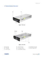
Figure 1 Overview ........................................................................................................................................... 7
Figure 2
Overview ........................................................................................................................................... 7
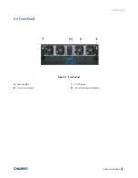
Figure 3
Front panel ........................................................................................................................................ 8
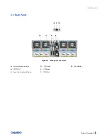
Figure 4 Back panel overview ......................................................................................................................... 9
Figure 5
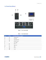
Front control panel ......................................................................................................................... 10
Figure 6
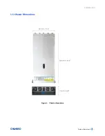
Chassis dimensions ......................................................................................................................... 11
Figure 7
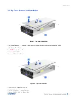
Top cover installation ...................................................................................................................... 16
Figure 8
Top cover removal ........................................................................................................................... 16
Figure 9
3.5” hot-swap HDD assembly installation ....................................................................................... 17
Figure 10
3.5” hot-swap HDD assembly removal ......................................................................................... 17
Figure 11
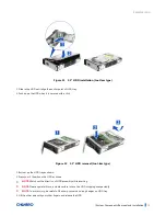
3.5” HDD installation (tool-less type) ........................................................................................... 18
Figure 12
3.5” HDD removal (tool-less type) ................................................................................................ 18
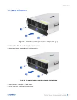
Figure 13 Installation of whole system into the rack (tool-less type) .......................................................... 19
Figure 14
Removal of whole system from the rack (tool-less type) ............................................................. 19
Figure 15 Front fan module installation (8038) ............................................................................................ 20
Figure 16 Front fan module installation (8038) ............................................................................................ 20
Figure 17 Front fan module removal (8038) ................................................................................................. 21
Figure 18 Front fan module removal (8038) ................................................................................................. 21
Figure 19 Middle fan modules Installation (8038) ........................................................................................ 22
Figure 20 Middle fan modules removal (8038) ............................................................................................. 22
Figure 21 Rear fan modules installation (8038) ............................................................................................ 23
Figure 22 Rear fan modules removal (8038) ................................................................................................. 23
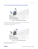
Figure 23 Internal expander card installation ............................................................................................... 24
Figure 24 Internal expander card removal .................................................................................................... 24
Figure 25 CRPS PSU installation .................................................................................................................... 26
Figure 26 CRPS PSU removal ......................................................................................................................... 26
Figure 27 Slide rail installation-1 (84H314610-003) ..................................................................................... 27
Figure 28
Slide rail installation-2 (84H314610-003) ..................................................................................... 27
Figure 29
Slide rail installation-3 (84H314610-003) ..................................................................................... 28
Figure 30
3.5” Drive tray/internal expander drive tray LED identification ................................................... 29
Figure 31
Backplane front view (front-right) ................................................................................................ 31
Figure 32 Backplane front view (front-left) .................................................................................................. 32
Figure 33 Backplane front view (rear-right) .................................................................................................. 33
Figure 34 Backplane front view (rear-left) .................................................................................................... 34


