background image

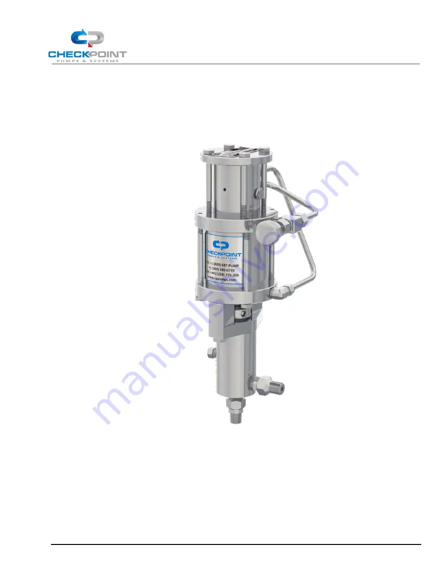
Series 1250 Pneumatic Chemical Injection Pump 

Operating Manual 

Page 1 of 19 

Series 1250 

Pneumatic Chemical Injection Pump 

Operating Manual 

Louisiana, US 

Aberdeen, UK 

21356 Marion Lane 

Unit C2 Lombard Centre 

Mandeville, LA 70471 

Kirkhill Place, Kirkhill Industrial Estates 

+1 (504) 340-0770

Dyce, Aberdeen, AB21 0GU Scotland 

+44 (0) 1224 775205

CP Pumps & Systems FZE 

Unit AA08, LIU 10

Jebel Ali 

South | PO Box 262131


 Dubai

 | 

UAE

+971 (4) 8806278 

CheckPoint Systems Pte Ltd 

21 Toh Guan Road East 

#04-17 Toh Guan Centre 

Singapore 608 609 

+65 6261 7687

CP/MAN-PRD-015       REV. 15        EFF. DATE: 07/08/2022

Summary of Contents for 1250 Series

Page 1: ...nit C2 Lombard Centre Mandeville LA 70471 Kirkhill Place Kirkhill Industrial Estates 1 504 340 0770 Dyce Aberdeen AB21 0GU Scotland 44 0 1224 775205 CP Pumps Systems FZE Unit AA08 LIU 10 Jebel Ali South PO Box 262131 Dubai UAE 971 4 8806278 CheckPoint Systems Pte Ltd 21 Toh Guan Road East 04 17 Toh Guan Centre Singapore 608 609 65 6261 7687 CP MAN PRD 015 REV 15 EFF DATE 07 08 2022 ...

Page 2: ...MP OPERATION 8 3 1 Bleeding Priming the Pump 8 3 2 Setting The Pump Stroke Rate 9 4 AIR GAS CONSUMPTION 13 5 PUMP MAINTENANCE 13 5 1 Packing Adjustment 14 5 2 Packing Replacement 14 5 3 Lubrication 16 6 TROUBLESHOOTING 17 6 1 Pump runs but chemical does not discharge at the correct rate 17 6 2 Pump does not stroke 18 6 3 Pump strokes erratically 18 6 4 Chemical leakage from packing nut 18 6 5 Othe...

Page 3: ...sions 1 PUMP INSTALLATION 1 1 Process Design Setup 1 1 1 Prior to installing your injector please inspect the pump carefully for any possible in transit damage If the pump appears damaged call your authorized CheckPoint distributor or call CheckPoint customer service directly at 800 847 7867 or 504 340 0770 to confirm damaged condition If we determine that damage has occurred in transit you will n...

Page 4: ... 1 1 6below 1 1 6 ALL VALVES FITTINGS AND PIPING BETWEEN THE SOURCE OF CHEMICAL AND THE PUMP S SUCTION CHECK VALVE MUST BE 100 BUBBLE TIGHT AND FULLY COMPATIBLE WITH THE CHEMICAL BEING DELIVERED AND WITH EACH OTHER FAILURE TO ADHERE STRICTLY TO THIS RULE WILL LEAD TO GAS BUILD UP IN THE CHEMICAL HEAD AND LOST PRIME SPECIFICALLY 1 1 6 1 Any fitting or screw on joint without TeflonTM tape or other a...

Page 5: ...k valve placed between a properly installed pump and the process flow the gas supply the chemical supply and in the case of Gas Recovery models the gas recovery outlet Conversely while the pump is running all such block valves should always be open 1 1 9 All process lines leading to and from the pump should be at least 3 8 inch diameter to ensure sufficient flow rates of chemical and minimize pres...

Page 6: ...roper adjustment is finger tight plus 1 6 of a turn Use a packing adjustment tool available from CheckPoint at no charge for best results IMPORTANT PLEASE REVIEW Section 5 1 Packing Adjustment on page14 1 2 5 Open the process block valve allowing the process pressure to reach the chemical head Correct any leakage observed 1 3 Connecting The Supply Gas 1 3 1 Gas supply to the pump should be clean c...

Page 7: ...ain switching valve components In situations where sand dirt and other particulate matter may be carried in with the supply gas a CheckPoint ST Series In Line Filter or a gas scrubber is recommended NOTE To find the Amplification Ratio for your pump please see Figure 2 below NOTE If this formula yields a result of 20 PSIG use 20 PSIG as your supply pressure pump does not require a pressure regulat...

Page 8: ... supply pressure in PSIG use the following formula RECOVERY PRESSURE SUPPLYPRESSURE DISCHARGE PRESSURE 30PSIG AMPLIFICATION RATIO 2 1 2 For a GR pump the maximum recovery pressure based on a supply pressure of 200 PSIG the maximum allowable supply pressure is given by MAXIMUM RECOVERY PRESSURE 170 PSIG DISCHARGE PRESSURE AMPLIFICATION RATIO 2 1 3 For more information on how to set up a recovery sy...

Page 9: ...one full minute of pumping has taken place However if the liquid level drops too fast to allow for a full minute shorter periods are acceptable Try to size the gauge so that at least a 30 second test can be made however or a loss of accuracy will result 3 2 1 2 Proper gauge placement and plumbing is important Please refer to Figure 1 for appropriate valving and placement and for reference numbers ...

Page 10: ...Supply Valve 3 2 1 7 Write down the amount of time in seconds and the final gauge reading then close the Gauge Fill Valve 3 2 1 8 The pumping volume in the units specified on the gauge scale will be given by the following equation PUMPING VOLUME END READING BEGINNING READING X 60 DURATION OF READING IN SECONDS 3 2 2 Calculation of Stroke Rate It is possible to calculate your pump s required stroke...

Page 11: ...G 3 2 2 2 Volume per stroke decreases as the discharge pressure rises It is necessary to apply a Volume De Rating Percentage VDP tothe Unrated Stroke Rate USR The VDPis based on the expected discharge pressure the pump will experience Use the VDP Graph Figure 5 to find the VDP taking care to use the curve for your specific plunger diameter 3 2 2 3 Use the resulting VDP to calculate the Target Stro...

Page 12: ...per minute rate 3 2 2 4 Finally ensure that the Target Stroke Rate does not exceed the maximum recommended stroke rate If the Target Stroke Rate exceeds the maximum recommended stroke rate for the type of service you intend it will be necessary to use a larger plunger size FIGURE 6 MAXIMUM RECOMMENDED STROKE RATE SERIES 1250 TYPE OF SERVICE MAXIMUM RECOMMENDED STROKE RATE CONTINUOUS USE 105 STROKE...

Page 13: ...as recovery options Use the following equation along with the appropriate gas consumption factor from Figure 7 to calculate air gas consumption GasConsumption SCFM 68F ChemicalFlowRate GPH GasSupplyPressure PSIA EnglishGas Consumption Factor Gas Consumption Nm3 Hr 0C Chemical Flow Rate LPH Gas Supply Pressure BARA SI Gas Consumption Factor FIGURE 7 GAS CONSUMPTION FACTORS GAS CONSUMPTION FACTOR PU...

Page 14: ...sary 5 1 1 Use a CheckPoint T55 101 packing adjuster which is specifically designed for this purpose If one is not available you may order one at no charge directly from CheckPoint In an emergency or if time is short a 6 length of OD tubing or metal rod may be used 5 1 2 It is highly recommended that the packing is adjusted while the pump is not running 5 1 3 To tighten the packing insert the tool...

Page 15: ...nternal packing nut threads end 5 2 7 Remove the suction check valve from the head 5 2 8 Using the suction check valve hole for access use a punch or screwdriver to push out the packing and sleeve 5 2 9 On the 1 8 and 3 16 plunger sizes remove the packing from the sleeve along with the O ring and backup ring on the small outside diameter of the sleeve Removal of O ring and backup ring for the 1 8 ...

Page 16: ...he threads on the two head bolts then insert and hand tighten them 5 2 18 Tighten the packing nut to the point where light pressure with one finger on the packing nut adjuster will no longer move the packing nut 5 2 19 Fully tighten down the head bolts Failure to adhere to this procedure can lead to a misaligned head and leaking packing 5 2 20 Reattach all process lines to the chemical head and op...

Page 17: ...G 6 1 Pump runs but chemical does not discharge at the correctrate 6 1 1 Suction check valve may be clogged with debris To flush open speed control valve fully allow pump to stroke at this maximum rate for at least 60 seconds then return to the original setting If no improvement is noted after three repetitions remove the suction check valve from body of pump blow out with air or water pressure or...

Page 18: ...h the air gas inlet may be absorbed by the standard spool material causing it to swell If after removal of the housing with the spool still inside the spool will not move with light finger pressure inside the housing call CheckPoint to order a replacement spool made of a different material 6 2 6 After a repair alignment screw may have been incorrectly reinstalled Ifcare is not taken to replace the...

Page 19: ...ntact your authorized CheckPoint distributor or call CheckPoint directly at 800 847 PUMP or 504 340 0770 to determine appropriate next steps Once CheckPoint has had the opportunity to help you troubleshoot your problem please keep in mind the following regarding repairs 6 5 1 CheckPoint offers an exchange program to keep you in service We will ship you a rebuilt pump which you will be able to inst...

Reviews: