background image

Microcontroller-Café  Checkpoint LAB                                                         
                                             

© Checkpoint LAB 2011                                                                                      

7


Be patient for few seconds until new one “pop-up bubble” confirmation message will appear:  


Figure 8. New hardware is ready to use  


Congratulations!

 Virtual COM Port Driver is ready to use with USB-RS232   converter.  

Please make current installation clear for yourself and verify it


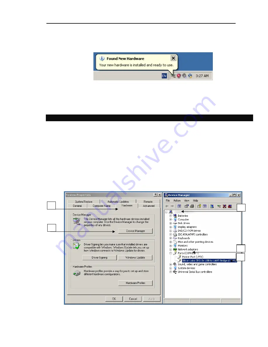
4.3 Virtual COM port driver installation check 


Follow to the verification steps: 


1.


Click “My computer” icon on your Desktop or click menu “Start” -> select “Properties” from 
pop-up menu 

2.


Select “Hardware” tab of “System properties” dialog 

3.


Click “Device manager” button 

4.


Expand tree of “Device manager”  

5.


Expand branch named “Ports (COM & LPT)”  

6.


In case of successful installation you’ll see node named “Silicon Labs CP210x USB to UART 
Bridge (COM3)” *** 


Figure 9. Virtual COM port in Device Manager 


4

5

6

Summary of Contents for Microcontroller-cafe USB-RS232

Page 1: ...Microcontroller Café Checkpoint LAB Checkpoint LAB 2011 USB RS232 CONVERTER User s Guide ...

Page 2: ...F CONTENTS 1 INTRODUCTION 3 2 DEVICE OVERVIEW AND FEATURES 3 3 SYSTEM REQUIREMENTS 4 4 INSTALLATION 4 4 1 Hardware interface 4 4 2 Virtual COM port driver installation 4 4 3 Virtual COM port driver installation check 7 5 PORT CONFIGURATION 8 APPENDIX 9 F TYPE M TYPE ...

Page 3: ...The USB RS232 converter board components READY device ready LED USB port connector DB 9 female serial port connector Figure 1 USB RS232 board layout 2 DEVICE OVERVIEW AND FEATURES The USB RS232 converter interface consists of the Tx transmit Rx receive data signals and the RTS CTS DSR DTR DCD RI control signals The UART supports RTS CTS DSR DTR and X On X Off handshaking If the Virtual COM Port dr...

Page 4: ...tion process step by step 4 1 Hardware interface Please follow the step by step installation procedure listed below Hardware interface 1 Connect one end of the USB cable to a USB port on the PC 2 Connect the other end of the USB cable to the USB connector on the USB RS232 converter 3 Connect the DB 9 connector to the target serial device Figure 2 Hardware setup 4 2 Virtual COM port driver installa...

Page 5: ... to the wizard Figure 4 Driver installer dialog 7 Click Change Install Location button 8 Select new installation directory among exiting directories under your hard drive or create new by clicking Make New Folder button 9 Or click Install button to continue default driver installation NOTE User can continue installation into default folder path for this case skip steps 6 8 or can change location i...

Page 6: ...is successfully completed you should see message window Installation completed successfully Figure 6 Click OK and USB2COM Converter Driver Installer will be automatically closed Figure 6 Installation completed 12 After finish steps you ll see pop up bubble message of the Task bar Figure 7 Figure 7 Found New Hardware system message 8 10 ...

Page 7: ...or yourself and verify it 4 3 Virtual COM port driver installation check Follow to the verification steps 1 Click My computer icon on your Desktop or click menu Start select Properties from pop up menu 2 Select Hardware tab of System properties dialog 3 Click Device manager button 4 Expand tree of Device manager 5 Expand branch named Ports COM LPT 6 In case of successful installation you ll see no...

Page 8: ... to change default settings follow to the next steps Figures 9 10 1 Click My computer icon on your Desktop or click menu Start select Properties from pop up menu Figure 9 2 Select Hardware tab of System properties dialog Figure 9 3 Click Device manager button Figure 9 4 Expand tree of Device manager Figure 9 5 Click node named Silicon Labs CP210x USB to UART Bridge COM3 6 Select Properties from po...

Page 9: ...anging Virtual COM port number 10 Click OK 11 Follow back to the Virtual COM port properties dialog Figure 10 12 Click OK to save settings changes APPENDIX USB RS232 converter schematic picture Figure 12 PCB top bottom side Figure 13 PCB bottom stands Figure 14 PCB dimensions Figure 15 USB port connector Figure 16 DB 9 port connector Figure 17 USB specification pins Figure 18 9 10 ...

Page 10: ...Microcontroller Café Checkpoint LAB Checkpoint LAB 2011 10 Figure 12 USB RS232 converter schematic picture ...

Page 11: ...Microcontroller Café Checkpoint LAB Checkpoint LAB 2011 11 Figure13 PCB top bottom side Figure 14 PCB bottom stands ...

Page 12: ... Figure 16 USB port connector Figure 17 DB 9 port connector M F Types Series A B pin Conductor Cable Wire 1 VBUS Vcc 5V RED 2 D WHITE 3 D GREEN 4 GND BLACK Shell Shield DRAIN WIRE Figure 18 USB specification pins Applicable for original specifications only M type compatible with AVR STK 500 starter kit ...

Reviews: