Korg Polysix MIDI Interface
Korg Polysix MIDI Interface
Korg Polysix MIDI Interface
Korg Polysix MIDI Interface
P6
P6
P6
P6----M
M
M
M Installation
Installation
Installation
Installation Manual
Manual
Manual
Manual
8
88
8----427 / v. 1.00
427 / v. 1.00
427 / v. 1.00
427 / v. 1.00
Copyright © 2021 CHD Elektroservis. All rights reserved.
No part of this publication may be reproduced in any form without the written permission of CHD Elektroservis.
7
77
7
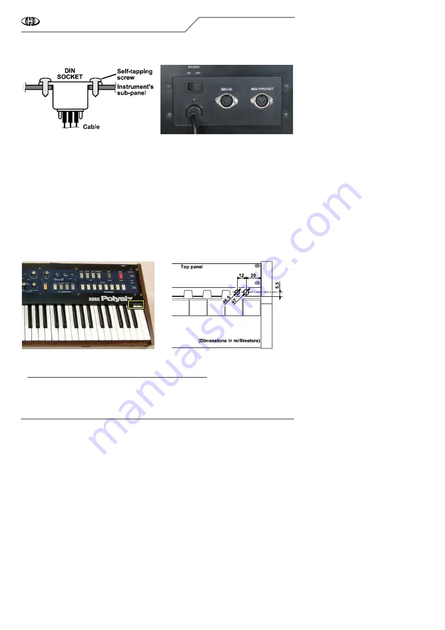
c) It is recommended to label the DIN sockets ("MIDI IN", "MIDI THRU/OUT" for example) with self-adhesive foil
glued near the sockets (fig. 2.2.5).
Fig. 2.2.4
Fig. 2.2.4
Fig. 2.2.4
Fig. 2.2.4
Fig. 2.2.5
Fig. 2.2.5
Fig. 2.2.5
Fig. 2.2.5
2.3
2.3
2.3
2.3 RESET BUTTON AND INDICATION LED INSTALLATION
RESET BUTTON AND INDICATION LED INSTALLATION
RESET BUTTON AND INDICATION LED INSTALLATION
RESET BUTTON AND INDICATION LED INSTALLATION
There are two control elements on the interface – reset button and indication LED. There are more possible
ways to install the button and the LED. The button and the LED need not be installed if you prefer to maintain
the vintage status of the instrument (i.e. if you don’t want to damage the instrument’s panel by drilling). Or you
can install only the reset button or only the indication LED (see chapter 3.2). Nevertheless having both of them
installed is more convenient for easier device control.
2.3.1
2.3.1
2.3.1
2.3.1 HOLES FOR
HOLES FOR
HOLES FOR
HOLES FOR RESET BUTTON AND INDICATION LED DRILLING
RESET BUTTON AND INDICATION LED DRILLING
RESET BUTTON AND INDICATION LED DRILLING
RESET BUTTON AND INDICATION LED DRILLING
a) If you decide to install the LED and the button, the suitable place for them is the right side of the front panel
of the instrument - above the highest keys (fig. 2.3.1).
b) Drill one hole with diameter 7 mm (for reset button) and one hole with diameter 6,5 mm (for indication LED)
to the panel – see fig. 2.3.2. Use sharp drills and work carefully
work carefully
work carefully
work carefully so that the panel is not scratched and other
parts of the instrument are not damaged during the drilling!
Fig. 2.3.1
Fig. 2.3.1
Fig. 2.3.1
Fig. 2.3.1
Fig. 2.3.2
Fig. 2.3.2
Fig. 2.3.2
Fig. 2.3.2
c) Clean the edge of the holes with small rasp or tip of bigger drill from both sides of the panel after the holes
are drilled.
d) Clean all iron sawdust and raspings from the inside of the instruments
Clean all iron sawdust and raspings from the inside of the instruments
Clean all iron sawdust and raspings from the inside of the instruments
Clean all iron sawdust and raspings from the inside of the instruments, they can cause short circuits or serious
electrical damage if they are left inside the instrument. Please clean the instrument carefully!


