62
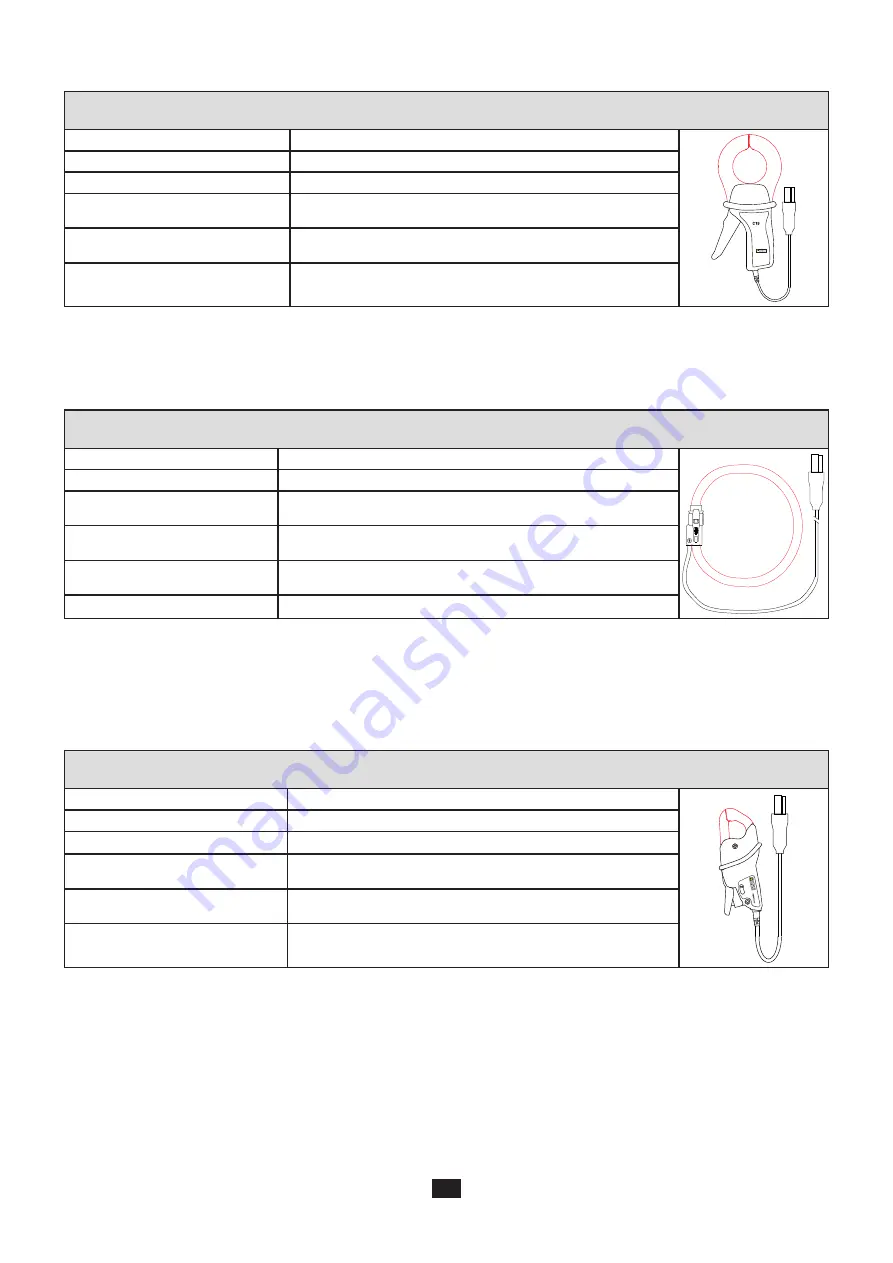
c) C193 clamp
C193 clamp
Nominal Range
1000 A
ac for f ≤1 kHz
3
CURRENT CLAMP
Measurement Range
0.5 to 1200 A
ac
max (I >1000 A more than 5 minutes)
Maximum Clamping Diameter
52 mm
Variation of the position of the
conductor in the clamp
< 0,1%, DC to 440 Hz
Adjacent conductor carrying
alternating current
> 40 dB typical at 50/60 Hz
Safety
IEC 61010-2-032, Pollution degree 2, 600 V CAT IV, 1000 V
CAT III
Table 16
Note:
Currents < 0.5 A will be set to zero.
d) AmpFlex
®
A193
AmpFlex
®
A193
Nominal Range
100 / 400 / 2.000 / 10.000 A
ac
Measurement Range
0.05 to 12000 A
ac
Maximum Clamping Diameter
Length = 450 mm; Ø = 120 mm
Length = 800 mm; Ø = 235 mm
Variation of the position of the
conductor in the sensor
>40 dB
any position and > 33 dB near snap device
Adjacent conductor carrying
alternating current
> 40 dB typical at 50/60 Hz everywhere and > 33 dB near the snap
Safety
IEC 61010-2-032, Pollution degree 2, 600 V CAT IV, 1000 V CAT III
Table 17
Note:
Currents < 0.05% of the nominal range will be set to zero.
The
nominal ranges are reduced to 50/200/1000/5000 A
ac
at 400 Hz.
e) MN93 clamp
MN93 clamp
Nominal Range
200 A
ac for f ≤1 kHz
M
N
9
3A
Measurement Range
0.5 to 240 A
ac
max (I >200 A not permanent)
Maximum Clamping Diameter
20 mm
Variation of the position of the
conductor in the clamp
< 0,5%, at 50/60 Hz
Adjacent conductor carrying
alternating current
> 35 dB typical at 50/60 Hz
Safety
IEC 61010-2-032, Pollution degree 2, 300 V CAT IV, 600 V CAT III
Table 18
Note:
Currents < 100 mA will be set to zero.
Summary of Contents for pel 102
Page 1: ...Power energy logger EN User s manual PEL 102 PEL 103 PEL 104 ...
Page 24: ...24 Aggregation period Date and time IP address scrolling Wi Fi address scrolling PEL104 ...
Page 36: ...36 Three phase 3 wire balanced 3P 3W b U12 U23 U31 f P Q S PF P Q S tan ϕ I1 I2 I3 ϕ I1 U12 ...
Page 38: ...38 Three phase 4 wire wye balanced 3P 4WYb I1 I2 I3 V1 V2 V3 VN U12 U23 U31 f P Q S tan ϕ ...
Page 39: ...39 DC 2 wire dC 2W DC 3 wire dC 3W P Q S PF ϕ I1 V1 P Q S tan ϕ P I V VN I1 I2 IN ...
Page 40: ...40 DC 4 wire dC 4W P I1 I2 I3 IN V1 V2 V3 VN V1 V2 VN ...
Page 48: ...48 Two phase 3 wire 1P 3W I1 I2 V1 V2 U12 VN P Q S P Q S ...
Page 51: ...51 P Q S ...
Page 85: ...85 ...


