12
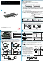
2.7. INSTALLATION OF THE COLOUR-CODED MARKERS
For multiple-phase measurements, start by marking the accessories and terminals with the colour-coded ID markers supplied with
the device; a different colour for each terminal.
Detach the appropriate inserts and place them in the holes under the terminals (larger inserts for current terminals, smaller
inserts for voltage terminals).
Clip rings of the same colour to the ends of the lead you will be connecting to the terminal.
Figure 8
2.8. CONNECTION FEATURES
Figure 9
Power cord connection.
SIM card slot (PEL 104 only).
USB connector.
Ethernet RJ 45 connector.
SD card slot.
Summary of Contents for pel 102
Page 1: ...Power energy logger EN User s manual PEL 102 PEL 103 PEL 104 ...
Page 24: ...24 Aggregation period Date and time IP address scrolling Wi Fi address scrolling PEL104 ...
Page 36: ...36 Three phase 3 wire balanced 3P 3W b U12 U23 U31 f P Q S PF P Q S tan ϕ I1 I2 I3 ϕ I1 U12 ...
Page 38: ...38 Three phase 4 wire wye balanced 3P 4WYb I1 I2 I3 V1 V2 V3 VN U12 U23 U31 f P Q S tan ϕ ...
Page 39: ...39 DC 2 wire dC 2W DC 3 wire dC 3W P Q S PF ϕ I1 V1 P Q S tan ϕ P I V VN I1 I2 IN ...
Page 40: ...40 DC 4 wire dC 4W P I1 I2 I3 IN V1 V2 V3 VN V1 V2 VN ...
Page 48: ...48 Two phase 3 wire 1P 3W I1 I2 V1 V2 U12 VN P Q S P Q S ...
Page 51: ...51 P Q S ...
Page 85: ...85 ...


