Chauvin Arnoux Multimetrix XDO 2040 User Manual Download Page 9

Instrument Description


Dual-Channel Digital Oscilloscopes 


Instrument Description (cont’d) 
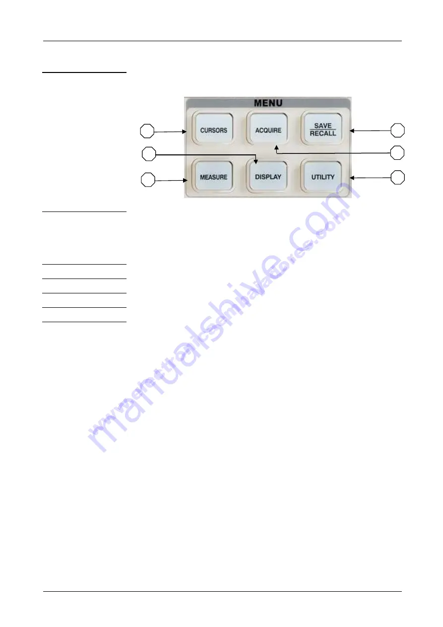
MENU key pad 


31 - CURSORS  

Displays the cursor menu (see p. 41). 
Vertical Position controls adjust cursor position while displaying the 
Cursor Menu and the cursors are activated. Cursors remain displayed 
(unless the “Type” option is set to “Off”) after leaving the Cursor menu 
but are not adjustable.


32 - ACQUIRE   Displays the Acquiring signal system 

(see p. 35).


33 - SAVE/RECALL  

Displays the Save/Recall Menu for setups and waveforms (see p. 48).


34 - MEASURE   Displays the Automatic Measurement menu 

(see p. 41).


35 - DISPLAY   Displays the Display menu 

(see p. 37).


36 - UTILITY 

Displays the Utility system 

(see p. 57).


33 

36 

32 

31 

35 

34 

Summary of Contents for Multimetrix XDO 2040

Page 1: ...c ch h ha a an n nn n ne e el l l 2 2 25 5 5 M M MH H Hz z z X X XD D DO O O2 2 20 0 04 4 40 0 0 2 2 2 c c ch h ha a an n nn n ne e el l l 4 4 40 0 0 M M MH H Hz z z U U Us s se e er r r s s s m m ma...

Page 2: ...ATH function menu 16 MATH function instruction 16 FFT Spectrum Analyser 17 FFT function menus 17 Select FFT window 17 Measuring an FFT Spectrum using cursors 18 Measuring an FFT amplitude 18 Measuring...

Page 3: ...rement 45 Auto measure function menu 45 Auto mode function menu Voltage measure 45 Auto mode function menu Time measure 46 Auto mode function menu Delay measure 46 All measurement function menu 47 Int...

Page 4: ...ature included between 10 C and 40 C with relative humidity up to 95 It can be supplied by a 240 V CAT II network definition of installation categories cf CEI 664 1 CAT I CAT I circuits are protected...

Page 5: ...the equipment He reserves the right to carry out repair or replacement of all or part of the equipment If the equipment is returned to the manufacturer forward transport is at the expense of the cust...

Page 6: ...Instrument Description 6 Dual Channel Digital Oscilloscopes Instrument Description Front panel XDO2025 XDO2040 16 15 17 11 9 10 7 8 18 14 13 12 6 5 4 3 2 1 16 15 3 10 9 11 8 7 18 14 13 12 1 2 17 4 5 6...

Page 7: ...TRIGGER Trigger system key pad see p 8 and 22 10 RUN STOP Continuously acquires waveforms or stops the acquisition 11 AUTO Automatically sets the oscilloscope controls to produce a usable display of t...

Page 8: ...L System 24 POSITION S div knob see p 21 25 HORI MENU Displays the horizontal menu 26 HORI knob Horizontal position knob see p 21 TRIGGER System 27 TRIG MENU Activates the Trigger menu 28 SET TO 50 St...

Page 9: ...sors are activated Cursors remain displayed unless the Type option is set to Off after leaving the Cursor menu but are not adjustable 32 ACQUIRE Displays the Acquiring signal system see p 35 33 SAVE R...

Page 10: ...cont d Rear panel XDO2025 37 Pass Fail PASS FAIL output 38 RS 232 RS 232 connector 39 USB Back USB connector 40 Plug Power input connector XDO2040 41 Pass Fail PASS FAIL output 42 RS 232 RS 232 connec...

Page 11: ...bered channel displayed when Autoset was invoked No signals found and no channels displayed the oscilloscope will display and use channel 1 Input a signal to Channel 1 press the Auto button Multi cycl...

Page 12: ...o Vectors for an FFT spectrum otherwise unchanged Vertical Coupling Adjusted to DC or AC according to the input signal Bandwidth Limit Off full V div Adjusted VOLTS DIV adjustability Coarse Signal inv...

Page 13: ...10 Hz GND disconnects the input signal BW limit XDO2040 only On Off Limits the bandwidth to reduce display noise filters the signal to reduce noise and other unwanted high frequency components Volts...

Page 14: ...tton to enter the Digital Filter menu Digital filter function menu Option Setting Description Digital Filter on off Turn on the digital filter Turn off the digital filter Turn the Universal knob to ad...

Page 15: ...vertical POSITION knob to set the vertical position to zero Volts div knob 1 Use the Volts div knobs to control how the oscilloscope amplifies or attenuates the source signal of channel waveforms When...

Page 16: ...eform Turn off CH1 Invert function CH2 Invert on off Invert the CH2 waveform Turn off CH2 Invert function By rotating the universal knob to adjust the vertical position of waveform after operation MAT...

Page 17: ...Window Speciality Satisfied Test content Rectangular Best frequency resolution worst magnitude resolution This is essentially the same as no window Symmetric transients or bursts Equal amplitude sine...

Page 18: ...g an FFT amplitude Once viewed the spectrum 1 Press the CURSOR button to enter Cursor menu 2 Press Cusor Mode to select Manual 3 Press Type to select Voltage 4 Press Source to select MATH 5 Press CurA...

Page 19: ...4 Press Source to select MATH 5 Press Cur1 turn the Universal button to move Cursor 1 to the highest position of the FFT waveform 6 The value of Cur1 displaying on the top right of the screen is FFT...

Page 20: ...n becomes available after a waveform has been saved REF function menu Press the REF button Option Setting Introduction Source CH1 CH2 CH1 off CH2 off Choose the waveform display to store REFA REFB Cho...

Page 21: ...elayed On Off Turn on this function in order to simultaneously display the main waveform time base on the top half of the screen and the window time base waveform on the bottom half of the screen Turn...

Page 22: ...led it changes the width of the window zone by changing the window time base Display scan mode When the SEC DIV control is set to 100 ms div or slower and the trigger mode is set to Auto the oscillosc...

Page 23: ...nected to the EXT TRIG front panel BNC and allows a trigger level range of 1 2V to 1 2V EXT 5 Same as Ext option but attenuates the signal by a factor of five and allows a trigger level range of 6V to...

Page 24: ...locks DC components and attenuates signals below 10 Hz HF Reject Attenuates the high frequency components above 80 kHz Coupling LF Reject Blocks the DC component and attenuates the low frequency compo...

Page 25: ...en Positive pulse width less than pulse width setting Positive pulse width larger than pulse width setting Positive pulse width equal to pulse width setting Negative pulse width less than pulse width...

Page 26: ...em cont d Pulse Trigger function menu 2 Option Setting Description Type Pulse Select the pulse to trigger the pulse match the trigger condition Mode Auto Normal Single Select the type of triggering No...

Page 27: ...g it then becomes possible to trigger the NTSC PAL and SECAM video signal CH1 CH2 Select the input source to be the trigger signal Source EXT EXT 5 Ext and Ext 5 use the signal applied to the EXT TRIG...

Page 28: ...ideo standard for sync and line number count Auto Use this mode to let the acquisition run in the absence of a valid trigger This mode allows an untriggered scanning waveform at 100 ms div or slower t...

Page 29: ...Slope Trigger function menu 1 Option Setting Instruction Type Slope Trigger on positive slope of negative slope according to setup time of the oscilloscope Source CH1 CH2 EXT EXT 5 Select trigger sour...

Page 30: ...can adjust LEVEL A LEVEL B or adjust them at the same time Auto Use this mode to let the acquisition run in the absence of a valid trigger This mode allows an untriggered scanning waveform at 100 ms d...

Page 31: ...nformation for the two channel signals is displayed at the bottom right of the screen Edge Trigger function menu Option Setting Instruction Type Alternative The trigger signal comes from two vertical...

Page 32: ...ative signals at the same time Source CH1 CH2 Set trigger type information for CH1 signal Set trigger type information for CH2 signal Mode Pulse Set trigger type of the vertical channel signal to Puls...

Page 33: ...related signals at the same time Source CH1 CH2 Set trigger type information for CH1 signal Set trigger type information for CH2 signal Mode Video Set trigger type of the vertical channel signal to Vi...

Page 34: ...usted by LEVEL knob You can adjust LEVEL A LEVEL B or adjust them at the same time Set up Enter the Trigger setup menu Option Setting Instruction Type Alternative The trigger signal comes from two ver...

Page 35: ...gnals to channel 1 and channel 2 2 Press the AUTO button 3 Press TRIG MENU to enter trigger menu 4 Press Type to select Alternative 5 Press Source to select CH1 6 Press S div to optimize waveform disp...

Page 36: ...Holdoff is the time between when the oscilloscope detects one trigger and when it is ready to detect another one If you want to change the holdoff time follow these steps 1 Press the TRIG MENU button...

Page 37: ...noise and decrease the possibility of aliasing Acquisition Average Use to reduce random or uncorrelated noise in the signal display Averages 4 16 32 64 128 256 Select number of averages Sin x x Sin x...

Page 38: ...button Option Setting Description Type Vectors Dots Vectors fills the space between adjacent sample points in the display Dots display sample points Directly Persist Off 1 sec 2 sec 5 sec Infinite Se...

Page 39: ...lays the vertical voltage in relation to time horizontal scale XY format displays a dot each time a sample is acquired on channel 1 and channel 2 Screen Normal Inverted Set to normal mode Set to inver...

Page 40: ...escription 40 Dual Channel Digital Oscilloscopes Functional Description DISPLAY System cont d Display system function menu 3 Option Setting Description Skin Classical Modern Tradition Succinct Set up...

Page 41: ...vertical POSITION set up the horizontal scale and position Turn the S div knob to adjust the sampling rate Range 5 kS s 200 MS s Option Setting Description Cursor Mode Manual In this menu set the man...

Page 42: ...ursor Measurement The cursor measurement has three modes Manual Track and Auto Press the CURSOR button Manual Cursor function menu Option Setting Description Cursor Mode Manual In this menu set the ma...

Page 43: ...the input signal channel that the Cursor B will measure Cur A Select this option turn the Universal knob to adjust horizontal coordinate of Cursor A Cur B Select this option turn the Universal knob to...

Page 44: ...ic measurements Follow these steps to perform auto cursor measurements 1 Press the CURSOR button to enter Cursor measure menu 2 Press the Cursor Mode option button to select Auto 3 Press the MEASURE b...

Page 45: ...to enter the Time measure menu Delay Press this button to enter the Delay measure menu All Mea Press this button to enter the All Measurement menu Return Press this option button to return the home pa...

Page 46: ...measure parameter Display the corresponding icon and measure value of your selected Voltage measure parameter Return Return to the first page of auto measurement menu Auto measure function menu 4 Dela...

Page 47: ...ment function to measure Delay parameters Return Return to the All Measure main menu Introduction of the measure type Measure Type Description Vmax The most positive peak voltage measured over the ent...

Page 48: ...he first cycle waveform Positive Duty Cycle is the ratio between positive pulse width and period Duty Measures the first cycle waveform Negative Duty Cycle is the ratio between negative pulse width an...

Page 49: ...eform interface image CSV file to a USB flash drive Setup data and waveform data can be recalled to the current oscilloscope or the other same model oscilloscopes Picture data and CSV files can t be r...

Page 50: ...pe The oscilloscope will recall this setup the next time you turn it on Press the SAVE RECALL button Save Recall setups to device Return to the last menu Modify the file name Option Setting Descriptio...

Page 51: ...he DISPLAY button to enter the Display menu 6 Press the Type option button to select Dots 7 Press the SAVE RECALL button to enter the SAVE RECALL menu 8 Press the Save option button Follow these steps...

Page 52: ...te a folder 7 Press Modify to modify a folder 8 Press New file to create a new file 9 Press Del file to delete a file 10 Press the next page and press the Rename to change the name of the file or the...

Page 53: ...ay the waveforms that you want to save The oscilloscopes can store twenty captured waveforms to a non volatile memory Save Recall waveform Option Setup Description Type waveforms Menu for the Save Rec...

Page 54: ...5 Turn the Volts div knob or S div knob to adjust the waveform that you want to save 6 Press Save Follow these steps To recall a saved waveform from the internal memory 1 Press the SAVE RECALL button...

Page 55: ...Insert the USB flash drive 5 Press Save to to select File 6 Press Save to enter the Save Recall interface 7 Create a file then press Confirm for about ten seconds 8 Press SAVE RECALL before removing t...

Page 56: ...RINT button to print the screen image Print Key Save Picture When the USB flash drive is inserted in the USB Host interface the USB flash drive open status icon will be displayed at the top of the scr...

Page 57: ...ing CSV files to a USB flash drive Data Depth Displayed Maximum Set to store displayed waveform data to CSV file Set to store maximum waveform data to CSV file Para Save On Off Set whether to store pa...

Page 58: ...n menu 1 Option Setting Description System Status Displays a summary of the oscilloscope settings Sound Open the key press voice Close the key press voice Counter On Off Turn on Frequency Counter Turn...

Page 59: ...eyboard detect program Run the dot lighting detect program Print Setup Enter the print setup menu to set print options Printer The oscilloscope is connected to the printer via a USB cable When you exe...

Page 60: ...on Update firmware You can update the oscilloscope using a USB flash Driver Pass Fail Press this button to enter the Pass Fail menu Record Press this button to enter the waveform record menu IO Settin...

Page 61: ...proceed as follows Set the switch to 1x on the probe and connect the probe to channel 1 on the oscilloscope To do this align the slot in the probe connector with the key on the CH 1 BNC push to connec...

Page 62: ...ect on Print the colour screen image when off is selected Layout Portrait Landscape Printer output layout Paper Size Default L 2L Hagaki Postcard Card Size 10 x 15 cm 4 x 6 8 x 10 Letter 11 x 17 A0 A1...

Page 63: ...13x18 cm 15x21 cm 18x24 cm A4 Letter Paper Type Default plain Photo Fast Photo Print Quality Default Normal Draft Fine ID Print Default On Off Displays Settings available on your PictBridge compatible...

Page 64: ...llow next steps 1 Insert the USB Flash Drive with firmware 2 Press the UTILITY button 3 Press Next Page to enter the third page of the Utility menu 4 Press the Update Firmware option button 5 Press th...

Page 65: ...within the predefined mask or not Pass Fail function menu 1 Option Setting Description Enable On Off Turn on Pass Fail function Turn off Pass Fail function Source CH1 CH2 Select Pass Fail test on CH1...

Page 66: ...ss Fail function menu 2 Option Setting Description Output Pass Fail Output when pass condition detected Output when fail condition detected Stop On Output On Off Stop test on output Continue test on o...

Page 67: ...et the range of horizontal clearance to the waveform 0 04div 4 00div Y Mask ydiv Turn the Universal knob to set the range of vertical clearance to the waveform 0 04div 4 00div Create Mask Create a tes...

Page 68: ...e Pass Fail menu 7 Press the Mask Setting button to enter the first page of Mask menu 8 Press X Mask turn the Universal knob to adjust the horizontal clearance 9 Press Y Mask turn the Universal knob t...

Page 69: ...tting Description Mode Record Play Back Off Set Record function menu Set Play Back function menu Turn off waveform recorder menu Source CH1 CH2 P F OUT Select record source channel Interval Set time i...

Page 70: ...tion Mode Play Back Set the Play Back function menu Operate Run Stop Press to start playback playing Press to stop playing Play Mode Set loop play mode Set single time play mode Interval Set time inte...

Page 71: ...of waveform This means that oscilloscope can save and replay the waveforms it captured This is similar to a waveform recording instrument and the largest recording size for its internal memory is 6M W...

Page 72: ...recalling function menu Option Description Stop Quit the auto recalled waveform the waveform in EMS memory can then be observed by changing the time base the waveform in EMS memory can be moved left a...

Page 73: ...H2 is displayed in lower half screen Record Mode Roll Single Sweep The recorder saves the channel waveform continuously the latter waveform will cover the former The recorder will stop saving when its...

Page 74: ...channel mode Peak measure With a low speed signal from 10 s div start it is possible to capture high frequency burr which are narrow to 10 ns Sampling mode Sample peak measure average Vertical XDO202...

Page 75: ...MHz bandwidth Trigger Type Edge pulse width video slope alternative Modes Auto normal single Coupling AC DC low frequency reject high frequency reject Level CH1 CH2 6 div from the middle of the screen...

Page 76: ...OVShoot FOVShoot RPREShoot FPREShoot rise time fall time frequency period Wid Wid Dut Dut BWid Phase FRR FRF FFR FFF LRR LRF LFR LFF Cursor measurements manual auto track Display settings Autoset Auto...

Page 77: ...er cord Safety As per EN 61010 1 2001 Isolation class 1 Pollution degree 2 Power supply overvoltage category 240 V EMC As per EN 61326 1 2006 Mechanical features Casing Dimensions XDO2025 305 x 133 x...

Reviews: