background image

20


Data Logger Model DL913 & DL914

4.1.1 MAX Mode

Selecting the MAX icon 

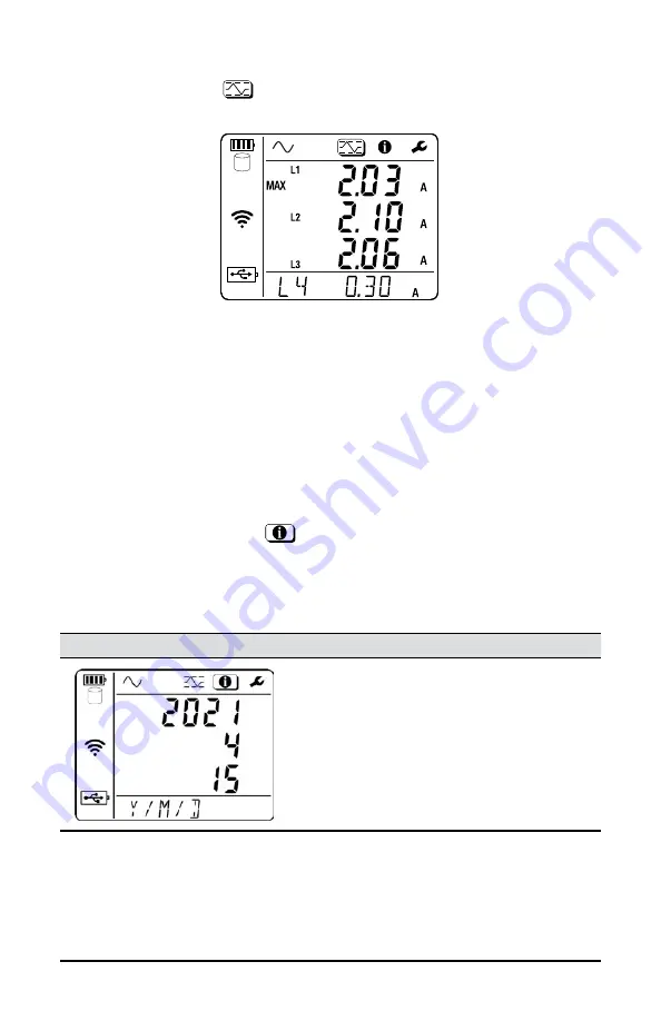
 displays the MAX mode screen. An example of the 

DL914 MAX mode screen is below:

This screen displays maximum aggregated averages over a period of time. For 

aggregation, certain measured values are averaged over a user-defined period. 

The MAX mode screen lists the highest aggregated average for a period for 

each probe.
Using the Data Logger Control Panel, you can determine whether the maximum 

aggregation is updated continuously or only when the instrument is actively 

recording. If it is set to update when actively recording only, the instrument will 

retain the current MAX value in its memory when the instrument is not recording 

but will not update it even if a higher aggregated value is encountered.

4.2 INSTRUMENT SETTINGS (INFORMATION MODE)

Selecting the Information icon 

 displays the Information mode screen that 

lists a number of instrument settings. 




Press the ▼ button to cycle through the settings.

The screens appear in the following order:

Screens

Description

See §

Date:

 for viewing only 

Can be changed using the Data 

Logger Control Panel software

§ 3.2.1

Summary of Contents for AEMC DL913

Page 1: ...Data Logger Models DL913 DL914 User Manual ENGLISH DATA LOGGERS WITH AEMC INSTRUMENTS ...

Page 2: ...742 2346 This documentation is provided as is without warranty of any kind express implied or otherwise Chauvin Arnoux Inc has made every reasonable effort to ensure that this documentation is accurate but does not warrant the accuracy or completeness of the text graphics or other information contained in this documentation Chauvin Arnoux Inc shall not be liable for any damages special indirect in...

Page 3: ...ime of purchase or obtained by returning the instrument to our repair and calibration facility for a nominal charge The recommended calibration interval for this instrument is 12 months and begins on the date of receipt by the customer For recalibration please use our calibration services Refer to our repair and calibration section at www aemc com Serial Catalog 2153 61 2153 62 Model DL913 DL914 P...

Page 4: ... CONFIGURATION 14 3 2 1 Time Date Setting 14 3 2 2 Enabling Disabling The Wi Fi 15 3 2 3 Measurement Settings 16 3 2 3 1 Current Range 16 3 2 3 2 Aggregation Period 16 3 2 3 3 Recording Mode 17 3 3 ERASING MEMORY 18 4 OPERATION 19 4 1 REAL TIME MEASUREMENTS 19 4 1 1 MAX Mode 20 4 2 INSTRUMENT SETTINGS INFORMATION MODE 20 4 3 RECORDING DATA 22 5 DATAVIEW 23 5 1 INSTALLING DATAVIEW 23 5 2 TYPES OF C...

Page 5: ...ICAL 29 6 2 MECHANICAL 30 6 3 ENVIRONMENTAL 30 6 4 SAFETY ELECTROMAGNETIC COMPATIBILITY 30 7 MAINTENANCE 31 7 1 CLEANING 31 7 2 REPAIR AND CALIBRATION 31 7 3 TECHNICAL ASSISTANCE 32 7 4 LIMITED WARRANTY 32 7 4 1 Warranty Repairs 33 ...

Page 6: ...ing dangerous voltages Type B current sensor as per IEC 61010 2 032 Important information to acknowledge USB socket This product complies with the Low Voltage Electromagnetic Compatibility European directives 73 23 CEE 89 336 CEE In the European Union this product is subject to a separate collection system for recycling electrical and electronic components in accordance with directive WEEE 2002 96...

Page 7: ...plosive atmosphere or in the presence of flammable gases or fumes Do not use on voltage networks greater than specified on the instrument label Do not use the instrument if it appears to be damaged incomplete or improperly closed Before each use check the condition of the insulation for the cables case and accessories anything that appears damaged even partially must be reported for repair or scra...

Page 8: ... power adapter quick start guide and USB thumb drive with DataView software and user manual Data Logger Model DL914 Cat 2153 62 4 Channel Includes small classic tool bag 10 ft USB A to B cable USB power adapter quick start guide and USB thumb drive with DataView software and user manual 1 3 1 Accessories and Replacement Parts Bag Small Classic Tool Bag Cat 2133 72 Cable 10 ft USB Cable Cat 2136 80...

Page 9: ...or USB connection Then the data can be analyzed using the Data Logger Control Panel Features include Three DL913 or four DL914 24 inch captive MiniFlex probes Waterproof IP 67 USB for communication and battery charging Wi Fi wireless communication 1000 V CAT III 600 V CAT IV The DL913 and DL914 are powered by two rechargeable NiMH batteries and can also be externally powered through a USB connecti...

Page 10: ... 2 2 Navigation buttons Up Down Left Right navigate the configuration options and measurement screens 3 Power button turns the instrument ON and OFF with a long press 5 s when the instrument is disconnected from external power and not actively recording A short press 3 s turns the LCD backlight on 4 Control button starts and stops recordings see 4 3 and selects and enables the Wi Fi communication ...

Page 11: ...ode indicators Configuration mode 3 2 Measurement mode 4 1 MAX mode 4 1 1 Information mode 4 2 2 Display for data and messages 3 Power ON Instrument is running on external USB power Blinking Instrument is running on external USB power and communicating via USB OFF Instrument is running on internal battery power 4 Permanent mode ON Permanent mode is enabled so the instrument will not automatically ...

Page 12: ...cording is pending Blinking slowly A recording is in progress in extended recording mode OFF A recording is neither scheduled nor in progress 9 Memory Empty Instrument memory is empty Partially filled Instrument memory is partially full Filled Instrument memory is full No recordings can be stored while the memory is full Please reference 3 3 for instructions to erase memory through the Control Pan...

Page 13: ... indicator If the indicator is full the battery is fully charged You can skip the remainder of this procedure If the indicator is partially full connect the instrument to an external power source via the USB cable 3 While the instrument is running on external power the battery will charge The battery indicator will blink to indicate that the battery is charging If depleted the battery will fully c...

Page 14: ...ory To enter Configuration mode press either or until the Configuration icon is highlighted There are two situations that prevent you from making changes in Configuration mode The instrument is being configured by the Data Logger Control Panel A recording session is in progress or scheduled If either situation applies you will not be able to enter Configuration mode and LOCKED will appear on the L...

Page 15: ...icon will appear on the screen for Wi Fi Direct The symbol will appear for connection to a router When you select a Wi Fi type it is automatically enabled on the instrument 3 To save battery life disable Wi Fi highlight the icon to enter Configuration mode or use the control button The Wi Fi screen is the first one displayed in Configuration mode Wi Fi requires a considerable amount of power so it...

Page 16: ...will also show 1 2 or 3 turns to indicate the instrument s configuration for the number of sensor turns wraps You can configure the instrument for the number of turns in the software only 2 Press to toggle between 360 A and 3600 A 3 2 3 2 Aggregation Period When recording data in normal recording mode see 4 3 the instrument performs measurement aggregation The instrument samples data at a fixed ra...

Page 17: ...run in normal recording mode or extended recording mode In both recording modes the instrument samples the inputs at a fixed rate every 200 ms and aggregates the samples every second The data is stored and displayed as 1 s values that represent trends Normal recording mode The instrument stores a sample every second Extended recording mode The instrument enters a sampling mode where the selected a...

Page 18: ...lly decreases battery life so the user should only enable Wi Fi when the device is externally powered 3 3 ERASING MEMORY When the memory indicator indicates the memory is full you will need to delete one or more recordings from memory to create room for the new recording You can only erase the memory through the Control Panel To delete memory the instrument must be connected to a computer 5 3 1 In...

Page 19: ...istribution system under test Each sensor is labeled L1 L2 and L3 for the DL913 L1 L2 L3 and N for the DL914 2 Connect each sensor to its corresponding phase For the DL914 you have the option to connect the L4 sensor to the distribution system s neutral 3 Press 3 s or connect to an external power source to turn the instrument ON 4 The Measurement screen is the first screen to appear The informatio...

Page 20: ...ggregation is updated continuously or only when the instrument is actively recording If it is set to update when actively recording only the instrument will retain the current MAX value in its memory when the instrument is not recording but will not update it even if a higher aggregated value is encountered 4 2 INSTRUMENT SETTINGS INFORMATION MODE Selecting the Information icon displays the Inform...

Page 21: ...puter when connecting to the instrument through Wi Fi The full address scrolls right to left at the bottom of the screen followed by the port number and communication protocol UDP or TCP 5 3 Battery Status lists the charging current charging voltage and remaining voltage of the battery 3 1 Firmware Revision lists the latest firmware revision running on the instrument N A ...

Page 22: ...to run with extended recording mode the measurements are limited to 4 times per the aggregation period to save battery Otherwise in normal recording mode measurements are stored once per second In either mode the recording will continue until Memory is full The internal memory can store around 2000 days of data As the memory fills the memory indicator will show how much storage space remains Keepi...

Page 23: ... will need to use Windows Explorer to locate and open the USB drive labeled DataView 2 When the folder is open double click Setup exe located in the root directory to open the Setup screen 3 In the upper left corner of the screen select your desired language for the installation process All setup screens and dialogs will appear in the selected language 4 Select DataView from the Options list and c...

Page 24: ... on your desktop and contain icons for the installed Control Panels After the Control Panel is installed you can connect your instrument to the computer to configure the instrument configure recording parameters schedule recording sessions start recording sessions and download the recorded data to the computer for analysis and report generation 5 2 TYPES OF CONNECTIONS The instrument provides thre...

Page 25: ...tings section according to your desired connection Enable DHCP instructs the instrument to obtain an IP address from the DHCP server on the currently connected network This option requires a DHCP server to be available on the network When Enable DHCP is checked the IP address Gateway address and Subnet mask fields are automatically filled and read only When Enable DHCP is unchecked you must to ent...

Page 26: ...3 Wi Fi Direct The Wi Fi Direct option requires the computer to be equipped with a Wi Fi radio and depends on the computer s model and operating system The computer will connect to the instrument directly without a router 1 Ensure that the Wi Fi Direct indicator is displayed on the instrument If not enable Wi Fi Direct as instructed in 3 2 2 2 On the computer create a direct Wi Fi connection to th...

Page 27: ...el consult the Help system that comes with the product 5 3 REMOTE USER INTERFACE The remote user interface is available via PC tablet or Android phone and allows you to view information about the device 1 Enable Wi Fi on the device The remote user interface can work with an access point Wi Fi link or a router Wi Fi link The remote user interface does not work with an IRD server link 2 On a PC conn...

Page 28: ...ents on each sensor and the network frequency In the Info tab you can view the device s date time location identifying information firmare version and current sensor information In the Recording tab you can view information about the in progress recording or the most recent recording ...

Page 29: ...e Rate Normal recording mode 1 sample per second Extended recording mode 4 samples per aggregation period Recording Length Battery Power 4 days with no missing samples normal recording mode 7 days to 30 days depending on the selected aggregation period extended recording mode External Power 365 days Memory Internal 8 GB Communication Options USB cable Wi Fi via router Ethernet Wi Fi Direct Wall Ch...

Page 30: ...out permanent mechanical damage and functional deterioration 6 3 ENVIRONMENTAL Operating Temperature 14 to 122 F 10 to 50 C Storage Temperature Without Batteries 40 to 158 F 40 to 70 C Relative Humidity Operation 0 to 85 RH Storage 0 to 95 RH Altitude Operation sea level to 6500 ft 2000 m Storage sea level to 32 000 ft 10 000 m Hazardous Substance RoHS3 Compliant 6 4 SAFETY ELECTROMAGNETIC COMPATI...

Page 31: ...r and calibration You must contact our Service Center for a Customer Service Authorization Number CSA Send an email to repair aemc com requesting a CSA you will be provided a CSA Form and other required paperwork along with the next steps to complete the request Then return the instrument along with the signed CSA Form This will ensure that when your instrument arrives it will be tracked and proce...

Page 32: ...warranty is given by AEMC Instruments not by the distributor from whom it was purchased This warranty is void if the unit has been tampered with abused or if the defect is related to service not performed by AEMC Instruments Full warranty coverage and product registration is available on our website at www aemc com warranty html Please print the online Warranty Coverage Information for your record...

Page 33: ...lete the request Then return the instrument along with the signed CSA Form Please write the CSA on the outside of the shipping container Return the instrument postage or shipment pre paid to Chauvin Arnoux Inc d b a AEMC Instruments 15 Faraday Drive Dover NH 03820 USA Phone 800 945 2362 Ext 360 603 749 6434 Ext 360 Fax 603 742 2346 or 603 749 6309 E mail repair aemc com Caution To protect yourself...

Page 34: ...NOTES ...

Page 35: ...NOTES ...

Page 36: ...AEMC Instruments 15 Faraday Drive Dover NH 03820 USA Phone 603 749 6434 800 343 1391 Fax 603 742 2346 www aemc com 12 22 99 MAN 100550 v0 Chauvin Arnoux Inc d b a AEMC Instruments All Rights Reserved ...

Reviews: