background image


COLORado™ Panel User Manual 

31 

8/19/2008 1:08 PM


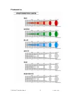
Photometrics 


Summary of Contents for COLORado Panel

Page 1: ...0 U S A 800 762 1084 954 929 1115 FAX 954 929 5560 www chauvetlighting com COLORado Panel USER MANUAL Snapshot OK on Dimmer Outdoor OK Sound Activated DMX512 Master Slave Autoswitching Transformer Replaceable Fuse User Serviceable Duty Cycle ...

Page 2: ... Setting up a DMX Serial Data Link 13 Master Slave Fixture Linking 13 4 Operating Instructions 14 Control Options 14 COLORado Control Quick Setup 14 DMX 512 control without ID address 14 DMX 512 addressing with ID address 15 COLORcon Setup 16 Setting the DMX address 17 Control Panel Functions 17 Over Heat Protection 17 Menu Map 18 DMX512 Channel Values 19 Important Notes about STAGE 1 DMX Operatio...

Page 3: ...cable 1 x DMX output cable 1 x Warranty Card 1 x User Manual Unpacking Instructions Immediately upon receiving a fixture carefully unpack the carton check the contents to ensure that all parts are present and have been received in good condition Notify the shipper immediately and retain packing material for inspection if any parts appear damaged from shipping or the carton itself shows signs of mi...

Page 4: ... dimmer pack Make sure the power cord is never crimped or damaged Never disconnect the power cord by pulling or tugging on the cord Avoid direct eye exposure to the light source while it is on Do not daisy chain power to more than 25 units 120volts Caution There are no user serviceable parts inside the unit Do not open the housing or attempt any repairs yourself In the unlikely event your unit may...

Page 5: ...lance Hyper Color RGBW color mixing with or without DMX controller Color temperature presets 3 200ºK 10 000ºK or create your own Built in automated programs via DMX Recall custom programs via DMX ADDITIONAL FEATURES High power 2W 390mA LEDs Available in white or black Hyper Color allows the LEDs to be driven at higher current for increased output Ingress Protection IP66 Additional power output max...

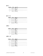
Page 6: ... ARC1 ARC1 D ARC 2 ARC2 D Each of the different personalities can be accessed from the control panel Please see section on Control Panel Functions on a description on how to accomplish this STAGE 1 CHANNEL DESCRIPTION 1 Dimmer 2 Red 3 Green 4 Blue 5 White 6 Color Macro White Balance Hyper Color 7 Strobe 8 Auto Custom Programs 9 ID Address Selection ARC 1 CHANNEL DESCRIPTION 1 Red 2 Green 3 Blue AR...

Page 7: ... User Manual 7 8 19 2008 1 08 PM ARC1 D CHANNEL DESCRIPTION 1 Dimmer 2 Red 3 Green 4 Blue ARC2 D CHANNEL DESCRIPTION 1 Dimmer 2 Red 3 Green 4 Blue 5 White HSV CHANNEL DESCRIPTION 1 Hue 2 Saturation 3 Value Intensity ...

Page 8: ...COLORado Panel User Manual 8 8 19 2008 1 08 PM Power Link Out DMX In pin Power In Power Out Control Panel Bracket Adjustment Hanging Bracket Floor Stand DMX Out Product Overview ...

Page 9: ...ble resistor or dimmer circuit even if the rheostat or dimmer channel is used solely for a 0 to 100 switch This fixture is designed for power linking from one COLORado Panel to another COLORado Panel fixture Each fixture ships with IP 66 proprietary power input cables Each fixture ships with a power adapter to Male Edison connector Warning All fixtures must be connected to circuits with a suitable...

Page 10: ...en you must use at least 1 safety cable chain for each fixture in addition to the mounting brackets If hanging the fixture for over head use then please follow the below steps 1 Block access below the work area and use suitable and stable platform when installing or servicing fixture 2 Safety cables must always be used secured through the heat sink ventilation passageway The safety cable must be c...

Page 11: ...s cover remove the screws that hold the lens assembly in place Note use care when performing this procedure as this gives you direct access to the LEDs which are very fragile 3 You now should have full access to the lens assembly This must be removed and the old lenses must be replaced with the new lenses The same assembly is to be reinstalled with the new lenses in place and the process is comple...

Page 12: ...able please use data grade cables that can carry a high quality signal and are less prone to electromagnetic interference DMX DATA CABLE Use a Belden 9841 or equivalent cable which meets the specifications for EIA RS 485 applications Standard microphone cables cannot transmit DMX data reliably over long distances The cable will have the following characteristics 2 conductor twisted pair plus a shi...

Page 13: ...Shield Pin 1 Pin 1 Data signal Pin 2 Pin 2 Data signal Pin 3 Pin 3 Do not use Do not use Do not use Do not use Setting up a DMX Serial Data Link 1 Connect the male 3 pin connector side of the DMX cable to the output female 3 pin connector of the controller 2 Connect the end of the cable coming from the controller which will have a female 3 pin connector to the input connector of the next fixture c...

Page 14: ... titled Display Panel Functions These steps assume that you have read and are familiar with setting up a DMX serial data link DMX 512 control without ID address The COLORado Panel operates on 9 channels of DMX STAGE1 personality Address each fixture in increments of 9 channels I e 1 10 19 28 etc To save time you can use the same DMX address for each fixture All fixtures will then respond simultane...

Page 15: ...nit independently by first selecting the DMX address and then by using Channel 10 to locate the target ID address Note that when using ID addresses it is also possible to activate ADAS which allows for even more option with DMX addressing and control DMX 512 addressing with ID address 1 Follow instructions 1 4 for DMX512 addressing 2 Activate ID addressing in each fixture by setting panel function...

Page 16: ...ID Address 09 ID Address 01 The figure above shows 9 fixtures connected in series Three rows comprised of 3 fixtures are addressed identically Each fixture has ID ON in the fixture s settings You must set the Range settings in the controller to 003 before accessing Effect programs ID Address 02 ID Address 03 ID Address 01 ID Address 02 ID Address 03 ID Address 01 ID Address 02 ID Address 03 Repeat...

Page 17: ...in control panel interface BUTTON FUNCTION MENU Exits from the current menu or function SET Enables the currently displayed menu or sets the currently selected value in to the selected function UP Navigates upwards through the menu list and increases the numeric value when in a function DOWN Navigates downwards through the menu list and decreases the numeric value when in a function Over Heat Prot...

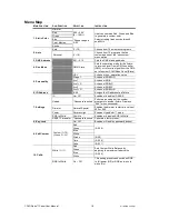
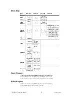
Page 18: ...age 1 9 channel RGBW D Arc 1 3 channel RGB Arc 1 D 4 channel RGB D Arc 2 4 channel RGBW Arc 2 D 5 channel RGBW D 6 ID Address 0 66 Assigns the ID address to a fixture 7 Settings ID On Off Enables or disables ID ADAS Upload Password required Performs an upload of the custom programs to another fixture Displays End when successful Dimmer Normal Special Enables the dimmer to start at a value of 000 o...

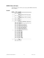
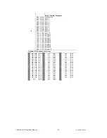
Page 19: ...31 150 151 170 171 190 191 200 201 205 206 210 211 215 216 220 221 225 226 230 231 235 236 240 241 245 246 250 251 255 Color Macro White Balance HyperColor No Function HyperColor Mode only in Normal power mode No Function Red 100 Green Up Blue 0 Red Down Green 100 Blue 0 Red 0 Green 100 Blue Up Red 100 Green 0 Blue Down Red 0 Green Down Blue 100 Red Up Green 0 Blue 100 Red 100 Green 0 Blue Down Re...

Page 20: ...0 069 070 079 080 089 090 099 100 109 110 119 120 129 130 139 140 149 150 159 160 169 170 179 180 189 190 199 200 209 210 211 All IDs ID 1 ID 2 ID 3 ID 4 ID 5 ID 6 ID 7 ID 8 ID 9 ID 10 ID 11 ID 12 ID 13 ID 14 ID 15 ID 16 ID 17 ID 18 ID 19 ID 20 ID 21 ID 22 212 213 214 215 216 217 218 219 220 221 222 223 224 225 226 227 228 229 230 231 232 233 234 ID 23 ID 24 ID 25 ID 26 ID 27 ID 28 ID 29 ID 30 ID ...

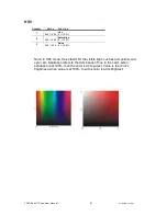
Page 21: ...d yellow and cyan etc Saturation refers to the dominance of hue in the color when saturation is at 100 then the color is at its purest Value is the color s brightness when value is at 100 then the color is at its brightest CHANNEL VALUE FUNCTION 1 000 255 Hue 0 100 2 000 255 Saturation 0 100 3 000 255 Value 0 100 ...

Page 22: ...e 0 100 CHANNEL VALUE FUNCTION 1 000 255 Dimmer 0 100 2 000 255 Red 0 100 3 000 255 Green 0 100 4 000 255 Blue 0 100 CHANNEL VALUE FUNCTION 1 000 255 Red 0 100 2 000 255 Green 0 100 3 000 255 Blue 0 100 4 000 255 White 0 100 CHANNEL VALUE FUNCTION 1 000 255 Dimmer 0 100 2 000 255 Red 0 100 3 000 255 Green 0 100 4 000 255 Blue 0 100 5 000 255 White 0 100 ...

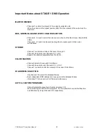
Page 23: ...ntrols the strobe of Channels 1 through 5 Channel 7 has priority over Channels 2 3 4 5 Speed of the strobe is adjustable from 0 to 20 Hz COLOR MACROS Channel 6 selects the required Color Macro Channel 6 has priority over Channels 2 3 4 5 7 Channel 1 is used to control the intensity of the current Color Macro ID ADDRESS SELECTION Use channel 10 to select ID addressed fixtures Each independent DMX a...

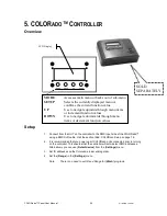
Page 24: ...PARATELY 5 COLORADO CONTROLLER Overview Setup 1 Connect from the OUT on the controller to the DMX Input side of the COLORado using a DMX XLR cable Visit the section titled COLORcon Setup on page 16 2 It is recommended that you power up all COLORado units connected prior to turning on the controller This ensures that the controller will auto detect DMX addresses Alternatively you can use Detect dev...

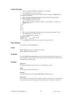
Page 25: ... I e 12 31 2006 13 50 24 Edit time I e 12 31 2006 13 50 24 Schedule Wash 1 Wash 8 Start End 00 00 00 00 Effect 1 Effect 8 Custom 1 Custom 8 Settings DMX address 001 255 Range 001 066 Allow edit YES NO Detect device Reset to Factory settings YES NO Password Password ON OFF ON OFF Set password Wash Program 1 Select from the eight existing Wash programs and it will instantly play 2 Set the Step time ...

Page 26: ...p time unit values Range 0 10 0 1sec per unit Range 11 255 1 sec per unit 9 Set a Fade time for the current scene in one second increments from 0 to 255 Play Schedule Simply activate this menu Play schedule to run Clock Clock Time now To view the current time on the controller Clock Edit now Edit the time and date Schedule There are 24 Wash Effect and Custom programs that can be set with Start and...

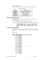
Page 27: ... password 3 Input an 8 digit password using the UP DOWN keys Press the SET button to confirm Note In the event that the user forgets the password use the following factory password override UP DOWN UP DOWN UP UP DOWN DOWN Control via external DMX Programs in the controller can be accessed via an external DMX controller It will be necessary to have the DMX address set on the COLORado Controller The...

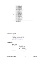
Page 28: ... Custom 4 Blackout Custom 5 Blackout Custom 6 Blackout Custom 7 Blackout Custom 8 4 000 127 128 255 OFF ON Technical Support Address Service Dept 3000 N 29th Ct Hollywood FL 33020 U S A Support Email tech chauvetlighting com Telephone 954 929 1115 Press 4 Fax 954 929 5560 Attention Service Website http www chauvetlighting com Contact Us World Wide General Information Chauvet Lighting 3000 North 29...

Page 29: ...er control multiple fixtures of the same type using the same starting address as long as the intended result is that of unison movement or operation In other words the fixtures will be slaved together and all respond exactly the same DMX fixtures are designed to receive data through a serial Daisy Chain A Daisy Chain connection is where the DATA OUT of one fixture connects to the DATA IN of the ne...

Page 30: ...g fluid Always dry the parts carefully Clean the external optics at least every 20 days Clean the internal optics at least every 30 60 days Returns Procedure Returned merchandise must be sent prepaid and in the original packing call tags will not be issued Package must be clearly labeled with a Return Merchandise Authorization Number RA Products returned without an RMA will be refused Call CHAUVET...

Page 31: ...COLORado Panel User Manual 31 8 19 2008 1 08 PM Photometrics ...

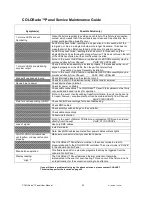
Page 32: ...iring internal and or external Device has no power Check device s fuse internal Check for power on Mains Check cable connections The COLORado Panel IP 66 cables must be firmly connected and locked in place for operation Note In the event of autoswitching transformer failure the unit can be sent in for repair however a replacement part can be ordered directly from Chauvet Part P140 CPELTR Fixture i...

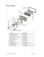
Page 33: ... Lens complete set CL18X10 15 30 3 LED Metal Core PCB complete P222 CPNLLED 4 LED Driver PCB P172 LEDPDVR 5 Electronic Transformer P140 CPELTR 6 Bracket Knob P111 C3HEXBLT 7 Display Master PCB P170 CPDSPL 8 Display Master IC chip P177 CPMICH not shown 9 Bracket Assembly P111 CPBRKT 10 Temperature sensor P111 80ITSNR not shown on PCB ...

Page 34: ...COLORado Panel User Manual 34 8 19 2008 1 08 PM ...

Page 35: ...n configuration pin 1 shield pin 2 pin 3 Protocols DMX 512 USITT DMX Channels User Configurable 3 4 5 or 9 STANDARD ORDERING INFORMATION COLORado Panel COLORADOPANEL 10 Optical Lens kit 18pcs CL18X10 15 Optical Lens kit 18pcs CL18X15 30 Optical Lens kit 18pcs CL18X30 IP68 power extension cable IP5POWER IP68 signal extension cable IP5SIG SPARE PARTS ORDERING INFORMATION Electronic Transformer Part ...

Reviews: