background image

6

Before making any connections, prepare batteries as follows:

(a)

With caps securely in place, thoroughly clean the case and posts with a solution of
baking soda and water. Be careful not to allow any soda to get inside the case.

(b)

All posts, terminal and connections should be cleaned to a shiny bright finish, using
a wire brush or sand paper. This should be done periodically to assure maximum
conductivity.

Charge Cables #1 and #2

Each charge cable assembly is equipped with a temperature sensor located at the junction
of each set of ring terminals. Attempts to lengthen or shorten the cables could partially dis-
able the charger. Therefore, we recommend that you do not make any adjustments without
first consulting the factory.

Route your cables from the charger to your batteries, being cautious to avoid sharp
objects and use the supplied wire ties to hold them neatly in place. Securely connect the
red (+) charger ring terminals to the positive battery posts and the black (-) charger ring
terminals to the negative posts. If the unit is equipped with a standard AC plug on the
power cord, a plug receptacle is also provided to hold the power cord plug when it is not
being used. Locate a convenient site for the receptacle and attach it using the four
smaller stainless steel screws.

Cranking Battery Cable

The cable assembly designated for the engine starting battery is unique in that in addition
to the Red (+) and Black (-) wires, there is a purple wire which must be attached to a 12
volt source that is switched on and off by the engine ignition key switch. Use the supplied
quick connector to attach the purple wire to any key activated 12 volt source. It is important
to note that the "charge on the run" circuitry will not operate unless the purple wire is connected
to a 12 volt source.

TROUBLE SHOOTING

PROBLEM: No LED indicators illuminate in any of the charger banks.

Solution Sequence:

Check the AC power supply from its source through all connecting points up to the charger
by using a meter or test light to confirm that current is being delivered to the charger.

PROBLEM: One red LED flashing.

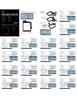
Negative

Negative

Negative

Positive

+

Positive

+

Power cord

Charge

Cable #2

Charge

Cable #1

Cranking

Battery

Cable

Purple

Wire

Positive

+

Summary of Contents for Dual Pro SE Xtreme

Page 1: ...5 10 10 10 15 15 6 2 2 3 3 Dual Pro SE Xtreme Dual Pro Xtreme Three Bank SE Xtreme Three Bank Pro Xtreme Model Name No of Banks Amps Per Bank Battery System 70201 installation and operating instructions for the following xtreme Battery chargers ...

Page 2: ...ndependent charging bank All of our chargers have true reverse polarity protection and shut off completely after each charge cycle TABLE OF CONTENTS Safety Instructions Page 2 4 Product Summary Page 4 5 Installation Instruction Page 5 6 Trouble Shooting Page 6 8 Warranty Information Page 8 IMPORTANT SAFETY INSTRUCTIONS SAVE THESE INTRUCTIONS This manual contains important safety and operating inst...

Page 3: ...water and soap nearby in case battery acid contacts skin clothing or eyes Wear complete eye protection and clothing protection Avoid touching eyes while working near battery If battery acid contacts skin or clothing wash immediately with soap and water If acid enters eye immediately flood eye with running cold water for at least 10 minutes and get medical attention immediately NEVER smoke or allow...

Page 4: ...ic Charging Systems International battery charging system Assure that your charger and batteries are properly vented Connect your extension cord with no AC Power present to the battery charger and proceed to plug your extension cord in at a nearby 120VAC GFCI protected Ground Fault Circuit Interrupt outlet Once you plug in your Charging Systems International battery charging system your batteries ...

Page 5: ... Do not make any electrical connections to the power supply AC or to a battery DC until the mounting process has been completed Check for fit and appropriate thickness of mounting area It is recommended that you choose a flat surface If a compartment wall is chosen make certain its strength is adequate Use the mounting flanges of the charger to mark locations for starter holes Drill a 1 16 inch ho...

Page 6: ... posts If the unit is equipped with a standard AC plug on the power cord a plug receptacle is also provided to hold the power cord plug when it is not being used Locate a convenient site for the receptacle and attach it using the four smaller stainless steel screws Cranking Battery Cable The cable assembly designated for the engine starting battery is unique in that in addition to the Red and Blac...

Page 7: ...me bank continues to malfunction please call the factory PROBLEM A green LED was illuminated before disconnecting the power from the charger but upon reconnection red LEDs appear and remain on This is normal operating procedure for the system and simply indicates that a re analysis of the battery status has been initiated and after a series of steps the green LED will illumi nate PROBLEM The indic...

Page 8: ...s International makes this Limited Warranty only to the original retail purchaser Charging Systems International warrants this battery charger for three years from the date of retail purchase against defective materials and or workmanship If such should occur this unit will either be repaired or replaced at the discretion of the manufacturer It is the responsibility of the original purchaser to re...

Reviews: