background image

Installing the Wall Dock

(3-gang Installation)

6

Installing the Wall Dock

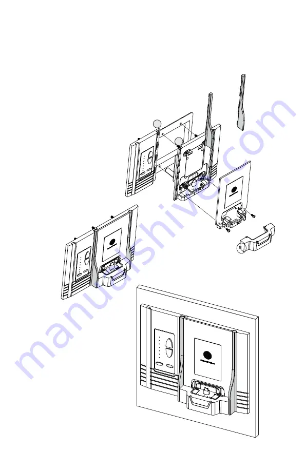
Installation Steps
1. Connect all wiring.
2. Attach main chassis to j-box using 
    the provided four 6-32 screws.
3. Feed the dock connector circuit
    board through the opening in the
    front cover.
4. Hang the front cover on the main
    chassis from the two top tabs.
5. Secure the front cover with the
    two small screws at the bottom.
6. Place the dock platform over
    the slide rail and push 
    downward until the retention 
    snaps are engaged.
7. Slide the side protectors
    into the slots on the main
    chassis.

Retention 

Snap

Slide Rail

2

2

4

3

5

6

6

7

5

2

1

In some installations it may be desirable to mount a single gang control 
keypad next to the A0317. To accomplish this, the single gang trim plate 
can be installed next to the A0317 in a 3-gang junction box.:

4

3

Completed Installation

7

Steps 3 & 4 complete

Steps 5 & 6 complete

Installation Steps:

1. Connect all wiring. Use the correct
    installation tools: J-110 tool, or 
    1014 crimp tool.
2. Install keypad and single-gang 
    trim plate in the far left position
    of the 3-gang junction box.
    (See details on page 3)
3. Leave off the right side 
    flange and trim piece. 
4. Install the iPod dock in the 
    left side of the 3-gang j-box.
    It will overlap and snap into
    the single gang trim plate.
    (See page 5 for details)

See attachment 
detail on previous page

3

Completed Installation

Summary of Contents for A0317

Page 1: ...A0317 Bluetooth Wall Dock for CAT5 Audio Systems Intelligent Entertainment Infrastructure Security Solutions...

Page 2: ...helps to hold the music player in place The A0317 adds elegant and contemporary styling to make it the perfect choice for anyone who wants to enjoy their music without defacing the wall 2 Front Top Fr...

Page 3: ...luded P 2044 power supply included A0240 A0302 In Room Amplifier Wiring Interface Source CHANNEL VISION Pwr 1 4 CAT5 Audio Distribution Module Required Power Optional Status System System Input Local...

Page 4: ...Input Zone 1 Zone 2 Zone 3 Zone 4 Expansion Output Local Priority Signal L R Emitters PRO CHANNEL TM VISION IR x TM CHANNEL VISION Model P 2014 A0125 P 2014 Tape Monitor or Room 2 output Optional IR...

Page 5: ...docking station These local input modules should be installed in the CAT5 line between the P 2014 and the A0125 Multiple input modules can be installed in one CAT5 run If audio is present at more than...

Page 6: ...ver 4 Hang the front cover on the main chassis from the two top tabs 5 Secure the front cover with the two small screws at the bottom 6 Place the dock platform over the slide rail and push downward un...

Page 7: ...stallation 7 Installation Steps 1 Connect all wiring Use the correct installation tools J 110 tool or 1014 crimp tool 2 Install keypad and single gang trim plate in the far left position of the 3 gang...

Page 8: ...ting CAT 5 Wire Blade Cat5 1 Place the CAT 5 between the blade and the first notch of the J 110 tool CAT 5 cable should be stripped with a proper stripping tool such as Channel Vision s J 110 tool Sli...

Page 9: ...wires to the power screw terminals on the side A0127 or A0129 A0350 Pwr Mute Vid 1 Vid 2 Vid 3 Vid 4 Vol Vol TM By CHANNEL VISION Aria Local In Active Spkrs 24VDC IR In Flush Mount Amplifier Left Rig...

Page 10: ...eaming Disconnecting The Dock A To disconnect the paired dock from your device disconnect the Bluetooth connection from the Bluetooth menu of the device Connecting The Dock To Another Device A Disconn...

Page 11: ...ssues Problem Hum in System Troubleshooting Plug all parts of the system into the same outlet to see if the hum goes away Try lifting the ground with a ground lifting plug Possible Cause The different...

Page 12: ...s a no hassle warranty with no mail in warranty card needed This warranty does not cover damages in shipment acts of God failures caused by other products not supplied by Channel Vision Technology or...

Reviews: