


Installation
4
5
Jumper Settings
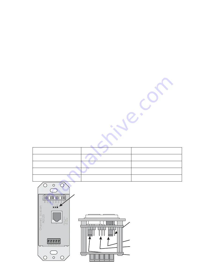
A0125 (Rear View)
Intercom jumper (Pin 1 is to the right)
Source Mode
A0125 (Bottom View)
Status Active (unused)
Volume Level
Pin 1 is to the right
(arrow is pointing at pin 1)
Pin 3 is to the left
(Jumper is on Pins 2 & 3)
Jumper settings determine how the A0125 will react under various
circumstances. These jumpers should be set to the desired configuration
before the A0125 is installed. If you need to make changes to the jumper
settings, the A0125 MUST BE DISCONNECTED from the system first.
Jumper setting functions explained:
Volume Preset
- This jumper determines the volume level the keypad will
be for music (no affect on the Intercom audio level) when it is turned on. If
the jumper is on pins 1 & 2, the volume will always be set at the default
level when the A0125 is turned on. If the jumper is on pins 2 & 3, the
volume will be at the same level as it was before the A0125 was turned
off.
Status Active
- This jumper is not active at this time on the A0125.
Source Mode
- This jumper determines if the A0125 will be used as a
multi-source keypad or a single-source keypad. If you are using the
keypad in a single source system, set the jumper on pins 1 & 2. If you are
using the keypad in a multi-source system, set the jumper on pins 2 & 3.
Intercom
- This jumper tells the keypad that it is connected to a hub with
integrated intercom functions. When in intercom mode, an intercom event
will cause the pwr LED to flash and the volume will change to its alternate
intercom volume level. While the pwr LED is flashing, volume changes on
the A0125 will alter the intercom volume level, which is independent of the
audio volume level.
Jumper Function
Volume Level
Status Active
Single-Source
Intercom
Default volume level
Previous volume level
(Not Used)
Jumper on Pins 1 & 2 Jumper on Pins 2 & 3
(Not Used)
Multi-Source
No Intercom
Source Mode
Intercom
Input Connectors
...
A0125 has both 110 and RJ-45 inputs. Only one
of the inputs should be used at a time.
To simplify installation, the
Output Connector
...
terminal is used to connect line level audio out to
the A0302 where it can be delivered to the A0240
for amplification. The Ground (G) and Power (PR)
terminals can be used to accept power from the
A0240 via the A0302. These terminals should only
be used if the A0125 is not connected to one of
Channel Vision’s CAT5 audio hubs.
This 5 position screw
Connect the A0125 to one of Channel Vision’s
CAT5 Audio Hubs. The CAT5 Audio Hub will
distribute line level audio and power to the A0125.
SUB L/R
R+
L+L-R-R+
R- L-
L+
JP1
JP2
JP3
GND
TB1
24V
PWR
GND
SW2
L/R
IN
SPKRS
IN
A0240
40Watt
Amplifier
A0125
(Rear)
A0302
(Rear)
Amp-Link
Cable
Speaker Level
Audio
Line Level
Audio
Note switch
positions
A0125 (Rear View)
NO INTNO INT
INTERCOM


