background image

16

PART 3:

OPERATION

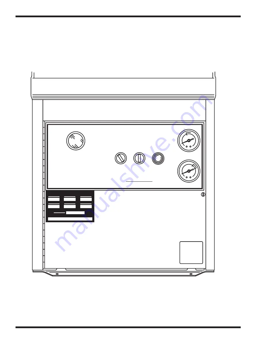
3.2 Description of Operator Controls and Indicators (Cont.)

3.2.2 Dishwasher

Figure 3.2

Controls and Indicators

Dishwasher

OFF

MANUAL

POWER

WATER LEVEL

RINSE

WASH

OFF

ON

START

WASH  TEMPERATURE

TURN POWER OFF BEFORE

SERVICING MACHINE

RINSE  TEMPERATURE

CYCLE

WARNING!

Champion

CHAMPION INDUSTRIES, WINSTON-SALEM, NC

Summary of Contents for USN-10

Page 1: ...I ...

Page 2: ...7 825 1202 Website www thesource2000 net Email Equipment Information HQ Darlene Ehrenfried darlene ehrenfried thesource2000 com Parts Information HQ Lori Hicks lori hicks thesource2000 com Service Information HQ Jim Luther jim luther thesource2000 com U S Navy POC Judy Lowman HQ judy lowman thesource2000 com U S Navy POC Nigel Pearce San Diego C nigel pearce thesource2000 com U S Navy POC Tony Cox...

Page 3: ...i TECHNICAL PUBLICATION SHEET TECHNICAL PUBLICATION SHEET ...

Page 4: ...ii TECHNICAL MANUAL VALIDATION CERTIFICATE TECHNICAL MANUAL VALIDATION CERTIFICATE ...

Page 5: ...iii APPROVAL AND PROCUREMENT RECORD APPROVAL AND PROCUREMENT RECORD ...

Page 6: ...iv TECHNICAL MANUAL DEFICIENCY EVALUATION REPORT TMDER TECHNICAL MANUAL DEFICIENCY EVALUATION REPORT TMDER Form NAVSEA 9086 10 REV 6 85 ...

Page 7: ...8 25 10 50 51 U2769 Revised illustration added note for supersession of overflow tube and screen ...

Page 8: ...3 47 All Replaced Items 4 6 switches with Kits 900856 900857 and 900858 respectively 10 3 13 61 All Pump motor seal and impleller no longer available as separate parts order Item 2 complete motor assembly Changed Item 4 to P N 108629 Item 7 to P N 115374 ...

Page 9: ...vii ...

Page 10: ...aintenance instructions contained in this manual are intended for qualified service personnel These instructions assume that you are trained in basic electricity and mechanical theory If you are not a trained technician then do not attempt to adjust or repair the dishwasher as serious personal injury or damage to the dishwasher may result CAUTION Caution statements indicate any condition or practi...

Page 11: ...ous voltages are present at the local electrical distribution system Dangerous voltages are present at the dishwasher when it is connected to the local electrical distribution system Pg 11 When working on the dishwasher disconnect the electric service and place a red tag at the disconnect switch to indicate work is being done on that circuit Pg 12 The installation of electrical supplies and contro...

Page 12: ... bromine or fluorine Mixing will cause hazardous gases to form Skin contact with deliming solutions can cause severe irritation and possible chemical burns Pg 27 Consult your chemical supplier for an appropriate deliming solution protective gear and safety procedures Pg 28 When working on the dishwasher disconnect the electric service and place a red tag at the disconnect switch to indicate work i...

Page 13: ...rform the following checks before placing the machine into service Pg 26 Do not hose down the exterior of the machine with water Pg 28 Only qualified service personnel should perform preventive maintenance on the dishwasher Pg 29 Only qualified service personnel should perform preventive maintenance on the dishwasher Pg 35 Only qualified service personnel should perform preventive maintenance on t...

Page 14: ...ing of utility supply valves or switching of electrical supply current g Cleaning of valves strainers screens nozzles or spray pipes h Performance of regular maintenance and cleaning as outlined in operator s guide i Damages resulting from water conditions accidents alterations improper use abuse tampering improper installation or failure to follow maintenance and operation procedures j Wear on Pu...

Page 15: ...Electrical Power Requirements Steam Heat Connections Between Dishwasher and Booster Steam Only Steam and Condensate Connections Steam Heat Only 3 2 1 Control Cabinet ...

Page 16: ...Final Rinse Steam Thermostat Adjustment and Replacement Fuses and Fuse Block Replacement ...

Page 17: ...c Tank Heat Assembly Prior to S N G3599 Electric Tank Heat Assembly After S N G3600 Electric Tank Heat Assembly After S N U2769 Control Cabinet Prior to S N G3599 No 180 Steam Booster and Steam Piping Assembly ...

Page 18: ...xvi TABLE OF CONTENTS This Page Intentionally Left Blank ...

Page 19: ...hwasher and describes the connection of utilities and services Part 3 Operation discusses theory of operation operator controls initial start up and shutdown procedures Part 4 Maintenance and Cleaning discusses lubrication preventive maintenance cleaning and deliming Part 5 discusses basic troubleshooting and service procedures Part 6 discusses replacement parts procurement and provides parts diag...

Page 20: ...Two electrical connections ...

Page 21: ......

Page 22: ...t Electrical Connection USN 10 440 60 3 70 F E 26 Amps 40 Amps Two Point Electrical Connection Machine USN 10 440 60 3 6 Amps 15 Amps Two Point Electrical Connection Booster USN 10 440 60 3 70 F E 20 Amps 25 Amps ...

Page 23: ...her with booster are shipped on a single pallet The booster is connected to the dishwasher Perform the following steps to unpack the dishwasher 1 Remove protective wrap and hold downs from the pallet 2 Inspect for any shipping damage If damage is found save the packing material and contact the carrier immediately 3 Check the interior of the dishwasher for the following items stowed inside 1 set of...

Page 24: ...plumbing connections between booster and dishwasher 6 Mount control cabinet to location nearest machine if applicable 7 Install deck plates and bolt dishwasher and booster to deck per standard procedures 2 3 Connections between the dishwasher and booster Steam Only WARNING The installation of this unit must conform to local codes or in the absence of local codes to the National Electrical Code and...

Page 25: ...7 PART 2 INSTALLATION This Page Intentionally Left Blank ...

Page 26: ...te Connections Steam heat only Perform the following steps to connect the steam supply and condensate return WARNING The installation of steam supplies must conform to local codes or in the absence of local code all National Codes governing plumbing sanitation safety and good trade practices NOTE A manual shut off valve for steam supplied by others should be installed in the supply lines to allow ...

Page 27: ...9 PART 2 INSTALLATION This Page Intentionally Left Blank ...

Page 28: ...1 The USN 10 undercounter dishwasher does not require a ventilation connection ...

Page 29: ...sconnect switch to indicate work is being done on that circuit 1 A qualified electrician must compare the electrical power supply with the machine electrical specifications stamped on the MACHINE ELECTRICAL CONNECTION PLATE located inside the control cabinet before connecting to the incoming service through a fused disconnect switch 2 Locate the dishwasher main electrical junction box for the mach...

Page 30: ...ING When working on the dishwasher disconnect the electric service and place a tag at the disconnect switch to indicate work is being done on that circuit 1 Chemical dispensing signal connection points are provided in the control cabinet 2 The detergent signal is limited to a maximum load of 1 Amp Signal voltage is 120VAC 3 The Rinse aid signal is limited to a maximum load of 1 Amp Signal voltage ...

Page 31: ...13 PART 2 INSTALLATION This Page Intentionally Left Blank ...

Page 32: ...nk A recirculating pump draws water from the tank and directs the water under pressure through the spray system and on to the dishes Wash water is heated in the tank by a steam coil or electric tank heater The final rinse water for sanitizing is heated in an external steam or electric booster heater The final stage of the washing operation occurs during the final rinse cycle Upper and lower final ...

Page 33: ...onnects power to tank and booster heat circuits pump contactors Power ON light Red pilot Signals control power connected to unit if ON OFF selector ON Start switch Green Initial Auto Fill Pushbutton Starts Pump Wash Rinse Selector Manual operation Switch of wash and rinse CONTROL TYPE FUNCTION 1 2 3 4 Table 3 1 Controls and Indicators Control Cabinet ...

Page 34: ...dicators Cont 3 2 2 Dishwasher Figure 3 2 Controls and Indicators Dishwasher OFF MANUAL POWER WATER LEVEL RINSE WASH OFF ON START WASH TEMPERATURE TURN POWER OFF BEFORE SERVICING MACHINE RINSE TEMPERATURE CYCLE WARNING Champion CHAMPION INDUSTRIES WINSTON SALEM NC ...

Page 35: ...icates water level in wash gauges Water line visible in center of glass indicates correct water level in tank Tank water Scaled Indicates water temperature in temperature thermometer wash and rinse gauges dial Wash 150 F minimum Rinse 180 F minimum Final rinse 0 60 PSI Indicates final rinse water pressure gauge during the final rinse 20 22 PSIG minimum flow pressure Final rinse Scaled Indicates fi...

Page 36: ...water supply valves Check for leaks and take corrective action as required 11 Open the steam supply valves if applicable Check for leaks and take corrective action if required 12 Monitor the water level gauge Tank is full when the water line reaches the center of the gauge 13 Check the dishwasher for leaks 14 Turn the main power on at the breaker panel or fused disconnect switch for the dishwasher...

Page 37: ...en it is connected to the local electrical distribution system WARNING When working on the dishwasher disconnect the electric service and place a tag at the disconnect switch to indicate work is being done on that circuit 20 If rotation direction is incorrect reverse wires L1 and L2 on the disconnect switch side of the main electrical connection terminal block located inside the remote control cab...

Page 38: ...hwasher for normal operation Only qualified service technicians are authorized to bypass a safety device for the purpose of troubleshooting and repair NOTE Refer to the corresponding repair or adjustment procedure in Part 5 Basic Service if a safety device fails to function in the manner prescribed below Dishwasher Condition The dishwasher is full of water steam or electric heat energized and dish...

Page 39: ...21 PART 3 OPERATION This Page Intentionally Left Blank ...

Page 40: ...d repair NOTE Refer to the corresponding repair or adjustment procedure in Part 5 Basic Service if a safety device fails to function in the manner prescribed below Dishwasher Condition The dishwasher is full of water steam or electric heat energized and dishwasher power is on Temperature gauges indicate proper temperatures The pump is running Booster Low Temperature Check 1 Insert rack into the ma...

Page 41: ...silverware evenly in a single layer in a flat bottom rack 3 Do not overload dishracks 4 Open the door and slide the rack into the dishwasher Close and latch the door 5 Monitor the wash temperature gauges Wash tank temperature must maintain 150 F minimum 6 Monitor the final rinse temperature gauge as the dishrack begins the final rinse cycle Minimum temperature required is 180 195 F 7 Monitor the f...

Page 42: ...spray arm 7 Flush arms with water 8 Set spray arms aside 9 Flush interior of machine to remove debris on upper hood surfaces 10 Remove scrap screen from dishwasher interior 11 Flush both sides of screen in remote sink to remove accumulated debris 12 Flush interior of lower tank with fresh water to remove debris 13 Clean drain screen 14 Wipe interior of dishwasher including tank bottom 15 Remove an...

Page 43: ...ank water temperatures to reach operating temperature Wash tank temperature 150 F minimum 9 Scrap and prerinse wares Place in dishracks Do not overload racks 10 Press Green start button on control cabinet to start wash cycle Pump runs 11 Open door and slide dishrack into dishwasher 12 Check the final rinse temperature and the final rinse pressure during the final rinse 180 195 F 20 22 psig flow pr...

Page 44: ...your machine is faced with abnormal working conditions hard water or multiple shift operations 4 2 Daily Cleaning Schedules Every 2 Hours or After Each Meal Period 1 Drain the dishwasher 2 Flush interior with fresh water 3 Clean scrap screen and pump intake screen 4 Clean spray arm nozzles Every 8 Hours or at the End of the Day 1 Drain the machine 2 Flush interior with fresh water 3 Clean scrap sc...

Page 45: ...t cleaning results WARNING Deliming solutions or other acids must not come in contact with household bleach sodium hypochlorite or any chemicals containing chlorine iodine bromine or fluorine Mixing will cause hazardous gases to form Skin contact with deliming solutions can cause severe irritation and possible chemical burns WARNING Consult your chemical supplier for an appropriate deliming soluti...

Page 46: ... 22 WARNING When working on the dishwasher disconnect the electric service and place a tag at the disconnect switch to indicate work is being done on that circuit 4 Turn the power selector switch to OFF at the control cabinet 5 Drain the dishwasher if required and inspect the float switches and probes in the bottom of the tank Float switch should move freely Clean if necessary 6 Check the spray ar...

Page 47: ...ice and place a tag at the disconnect switch to indicate work is being done on that circuit 5 Disconnect the power to the dishwasher at the main service disconnect switch Tag the circuit to indicate work is being performed on that circuit 6 Open the control cabinet enclosure s and check the tightness of all electrical wiring connections 7 Inspect all wiring for signs of heat damage and replace if ...

Page 48: ...1 The USN 10 undercounter dishwasher does not require lubrication 4 5 Lubrication Schedules ...

Page 49: ...31 PART 4 CLEANING AND MAINTENANCE This Page Intentionally Left Blank ...

Page 50: ...s Champion places an electrical schematic in the control cabinet of every machine before it is shipped Schematics are included at the back of this manual as well Be aware that these schemat ics include options that may not apply to your machine Options are enclosed in dashed lines with the words IF USED next to them on the schematic Disregard any options that appear on the schematics which are not...

Page 51: ...vel low in tank s Check float switch and fill tanks Defective float switch Refer to Repair Procedure 5 3 5 Motor overload tripped Refer to Repair Procedure 5 3 17 Blown fuse or circuit breaker Refer to Repair Procedure 5 3 16 Low or no water Main water supply is turned off Turn on main water supply Machine not filled initially Close drains Open manual fill valves Tank overflow removed Reinstall ov...

Page 52: ...minimum for 70 rise booster 140 F minimum for 40 rise booster Booster steam supply shut off Turn on steam supply Booster water supply shut off Turn on water supply Rinse nozzle missing Replace missing part Defective final rinse thermostat Refer to Repair Procedure 5 3 10 Defective thermometer Refer to Repair Procedure 5 3 7 Low steam pressure Correct steam pressure is 15 30 PSI Defective steam sol...

Page 53: ...adjust the pressure setting on the PRV loosen the locknut on the adjusting screw in the top of the PRV Turn the adjusting screw clockwise to increase the pressure setting Turn the screw counterclockwise to decrease the pressure setting The USN 10 dishwasher requires a flowing pressure of 20 22 PSI during the final rinse With the dishwasher in normal operation place a dishrack in the machine While ...

Page 54: ...t the interior of the vacuum breaker Remove any mineral deposits and inspect the float seating surfaces for pitting If badly pitted replace the entire vacuum breaker assembly Install a new float repair kit and reassemble in reverse order Turn on power and water supplies Operate the dishwasher and check for leaks 5 3 4 Water Solenoid Valve Repair A 1 2 water solenoid is located in the final rinse w...

Page 55: ...ilts up to allow inspection and cleaning Lift up the hinged cover and inspect the overflow tube if an obstruction is suspected Item 10 shows the drain screen This screen should be inspected daily and cleaned Item 12 illustrates the drain assembly It consists of soldered copper pipe and if defective must be replaced as a unit Note the cleanout plug to the left of the drain valve This plug can be re...

Page 56: ... described above 5 3 9 Tank Heat High Limit Adjustment and Replacement Refer to Fig 6 4 Fig 6 5 and Fig 6 6 Part 6 Replacement Parts for the detailed drawing of the thermostat and high limit assembly The tank has two types of thermostats The tank heat thermo stat as described in 5 3 8 and a tank high limit thermostat The high limit thermostat protects the tank from overheating The high limit therm...

Page 57: ... from the line Turn power off to the dishwasher at the dishwasher control Remove the protective cap from the thermo stat body Note the location of the wires and disconnect Disconnect the conduit Remove the thermostat from the booster piping Install the replacement as shown in the diagram below Follow instructions as listed on Part 8 Service Bulletins on Page 91 Return the dishwasher to normal oper...

Page 58: ...tance range If the coil checks good then disas semble the valve by removing the four bolts in the valve bonnet Remove and inspect the valve piston and diaphragm Inspect the valve seat for mineral deposits and pitting Replace the complete valve assembly if pitting is severe Reassemble the valve in reverse order Turn on steam and power supplies and check for leaks 5 3 12 Steam Trap Repair and Replac...

Page 59: ...6 Gasket Flow header Special Tools Required Torque wrench 30 ft lbs needed To clean the heater tubes Turn off all power steam and water supplies to the booster and dishwasher Refer to Fig 6 16 Part 6 Replacement Parts Note Item 1 thermostats Remove the thermostat covers mark and discon nect the wires Remove the conduit and fittings Mark the location of each thermostat before removal then unscrew e...

Page 60: ...rotation is clockwise when viewing motor from the rear 20 Test run and check for leaks 5 3 15 Door Safety Switch Refer to Fig 6 1 Replacement parts item numbers 9 and 10 The door safety switch assembly consists of a magnet on the inside wall of the tank and a magnetic reed switch mounted to the bottom of the tank Studs are welded on the bottom of the tank and nuts hold the switch in place The magn...

Page 61: ...oads In addition an auxiliary set of switch contacts is built into the overload The switch contacts disconnect 120VAC power to the motor contactor coils in the event of an overload condition Refer to Fig X If the switch lever is off with the 0 showing then the overload has tripped on an overload To Reset the Motor Overload Flip the starter switch to the On position Run the dishwasher and test the ...

Page 62: ...net Factory Position of Jumpers All of the jumpers are set in the ON position by the supplier NOTE The service technician must change the jumper settings for proper operation of the machine The proper jumper positions are JB 1 OPEN JB 2 CLOSED JB 3 OPEN The photograph on the right shows jumper JB 1 being set to the open position The remaining jumpers must be set according to information above ...

Page 63: ...HQ Jim Luther jim luther thesource2000 com U S Navy POC Nigel Pearce San Diego CA nigel pearce thesource2000 com U S Navy POC Tony Cox Mayport FL tony cox thesource2000 com U S Navy POC Janet Searls Norfolk VA janet searls thesource2000 com The Source 502 Rotary Street Hampton VA 23661 Tel 1 757 825 1400 1 800 497 2144 Fax 1 757 825 1202 website www thesource2000 net ...

Page 64: ...ER LEVEL RINSE WASH T R A T S N O F F O WASH TEMPERATURE TURN POWER OFF BEFORE SERVICING MACHINE RINSE TEMPERATURE CYCLE WARNING Champion CHAMPION INDUSTRIES WINSTON SALEM NC 24 17 14 14 15 17 11 9 10 12 13 8 2 3 7 6 5 4 1 16 16 19 20 21 22 23 19 25 26 29 30 27 27 28 26 28 25 19 21 ...

Page 65: ... 2 17 110228 Pin Door 2 18 0309228 Reed Switch Bracket Not Shown 1 19 100003 Nut Plain 1 4 20 SST 5 20 0509251 Thumbscrew 1 4 20 x 2 3 4 SST 1 21 0501425 Screw 8 32 x 5 8 Round Head SST 4 22 0501497 Washer Split Lock 8 2 23 107965 Nut Grip 8 32 w Nylon Insert 2 24 0501419 Bolt 1 4 20 x 1 2 Hex Head SST 4 25 0501501 Lock Washer 1 4 4 26 114747 Catch Door Beginning with S N U10023393 1 27 107965 Gri...

Page 66: ...48 PART 6 REPLACEMENT PARTS Figure 6 2 Wash and Rinse Spray System 14 3 5 7 7 8 12 13 13 6 4 4 3 15 9 10 1 1 2 1 11 1 Back of Machine ...

Page 67: ...er Wash Arm 1 6 0507443 Spindle Lower Rinse Arm 1 7 113514 Bearing Rinse Arm 2 8 0710247 Rinse Arm 1 9 113220 Breaker Vacuum 1 2 1 10 108349 Kit Vacuum Repair 1 2 not shown 1 11 0710565 Manifold Rinse Piping Assy 1 12 0507444 Nut Rinse arm 1 13 104005 Nozzle Rinse Arm Rotating 4 14 0510269 Spindle Upper Wash 1 15 0510268 Spindle Lower Wash 1 0710089 Rinse Arm Assy includes 7 8 and 16 0710086 Wash ...

Page 68: ...2 1 1 4 3 4 Figure 6 3 Scrap Screen Pump Strainer and Overflow ...

Page 69: ...3 0710279 Tube overflow SST All Serial Numbers 1 4 107680 Seat overflow tube 1 Item No No Part Description Qty DESIGN CHANGE NOTICE NOTE For machines built prior to S N U2769 you must replace the overflow and the scrap screen Items 2 and 3 together For machines built after S N U2769 the overflow and the scrap screen Items 2 and 3 may be ordered separately ...

Page 70: ...52 PART 6 REPLACEMENT PARTS Figure 6 4 Electric Tank Heat Assembly Prior to S N G3599 1 2 3 7 5 8 6 4 9 10 ...

Page 71: ...escription Qty 1 109755 Heater 3KW 480V 1 2 108345 Gasket heater 1 3 111092 Switch float 1 4 111151 C clip 2 5 104584 Nut float switch retaining 1 2 13 Hex hd SST 1 6 113622 Thermometer 4 ft gas filled 1 7 201041 Washer 1 8 109069 Thermostat control 1 9 111151 C clip Float Switch 2 10 201029 Nut Lock 1 2 2 ...

Page 72: ...54 PART 6 REPLACEMENT PARTS Figure 6 5 Electric Tank Heat Assembly After S N G3600 1 2 3 7 5 9 7 6 8 10 4 10 12 13 14 11 ...

Page 73: ... Switch float 1 4 111151 C clip 2 5 104584 Nut float switch retaining 1 2 13 Hex hd SST 1 6 113622 Thermometer 4 ft gas filled 1 7 201041 Washer 1 8 109069 Thermostat control 1 9 110561 Thermostat fixed essex 1 10 201029 Nut Lock 1 2 3 11 100740 Bolt 5 16 18 x1 Hex Head 4 12 102376 Washer 5 16 x 3 4 x 1 16 4 13 106013 Washer Lock 5 16 Split 4 14 100154 Nut Plain 5 16 18 SST 4 ...

Page 74: ...56 PART 6 REPLACEMENT PARTS Figure 6 6 Electric Tank Heat Assembly After S N U2769 2 4 5 3 1 6 7 8 ...

Page 75: ...em No No Part Description Qty 1 104585 Nut float switch retaining 1 2 13 Hex hd SST 1 2 113622 Thermometer 4ft gas filled 1 3 201041 Washer 2 4 110561 Thermostat fixed essex 1 5 109069 Thermostat w capillary 1 6 201029 Nut Lock 1 2 3 7 111092 Switvh Float 1 8 111151 C clip Float Switch 2 ...

Page 76: ...58 PART 6 REPLACEMENT PARTS Figure 6 7 Steam Tank Heat Assembly After S N U2769 5 2 1 6 8 7 3 4 9 ...

Page 77: ...on Qty 1 0710564 Steam Coil Weldment Assy 1 2 111092 Switch float 1 3 111151 C clip 2 4 104584 Nut float switch retaining 1 2 13 Hex hd SST 1 5 113622 Thermometer 4 ft gas filled 1 6 110561 Thermostat fixed essex Used only on S N U2793 1 7 201041 Washer 2 8 109069 Thermostat control 1 9 201029 Nut Lock 12 3 ...

Page 78: ...60 PART 6 REPLACEMENT PARTS Figure 6 8 Pump and Motor Assembly 3 5 9 6 3 7 3 8 9 10 4 2 3 1 ...

Page 79: ...Motor Assembly Complete 1 Seal pump Not available separately order Item 2 N A Impeller pump Not available separately order Item 2 N A 3 0502563 Clamp hose 4 4 108629 Hose pump discharge 1 5 0509701 Fitting pump discharge 1 6 0309701 Fitting pump suction modified 1 7 115374 Hose pump suction 1 8 0309707 Plate pump mounting 1 9 107967 Nut grip 1 4 20 SST 4 10 106026 Washer flat 1 4 SST 4 ...

Page 80: ...62 PART 6 REPLACEMENT PARTS Figure 6 9 Control Cabinet Prior to S N G3599 1 2 3 4 5 7 6 8 10 10 11 11 12 12 1 13 9 2 14 14 ...

Page 81: ...22 Contactor 1 2 HP Wash motor 12A 3 pole 1 5 111904 Contactor booster heater 40A 3 pole 1 6 106925 Block fuse 30A 3 pole 1 7 100906 Fuse 5A 480V 3 3 8 106402 Block fuse 2 pole 1 9 0508707 Fuse 1A 480V 3 2 10 109069 Thermostat control 1 11 0509706 Circuit Board 1 12 108311 Breaker circuit 3A 1 13 0309745 Box control 1 14 111036 Socket Relay 2 15 0508708 Fuse 2 5Amp 600V Not Shown 2 103309 Wire lug...

Page 82: ...ART 6 REPLACEMENT PARTS CONTROL TRANSFORMER 120V 120V 120V 120V F1 GND 1 18 BOOSTER CONTACTOR TANK HEAT CONTACTOR 14 9 8 7 12 17 16 15 13 10 11 3 4 5 1 6 2 19 Figure 6 10 Control Cabinet After Serial G3600 ...

Page 83: ...Wire Lug Ground 1 7 111827 Contactor 60 FLA 3P 120 Coil Tank Heat 1 8 100906 Fuse ATMR 5 600V One Time 3 9 112901 Fuse ATDR 1 Time Delay 2 10 106402 Block Fuse 2Pole 1 11 106925 Block Fuse 30A 3 Pole 1 12 111827 Contactor 60FLA 3P 120 Coil Booster Heat 1 13 111626 Starter Mtr 1 6 2 4 AMP 1 14 108130 Contact Auxiliary TM LA1 DN11 1 15 108122 Contactor 12A LC1D1210G6 1 16 111068 Relay 120V 4 17 1110...

Page 84: ...6 PART 6 REPLACEMENT PARTS Figure 6 11 Control Cabinet After Serial U2769 CONTROL TRANSFORMER 120V 120V 120V 120V 17 GND 1 BOOSTER CONTACTOR TANK HEAT CONTACTOR 9 8 7 12 18 16 15 13 10 11 3 4 1 6 2 14 5 ...

Page 85: ...al Block 1 6 103309 Wire Lug Ground 1 7 111827 Contactor 60 FLA 3P 120 Coil Tank Heat 1 8 100906 Fuse ATMR 5 600V One Time 3 9 112901 Fuse ATDR 1 Time Delay 2 10 106402 Block Fuse 2Pole 1 11 106925 Block Fuse 30A 3 Pole 1 12 111827 Contactor 60FLA 3P 120 Coil Booster Heat 1 13 111626 Starter Mtr 1 6 2 4 AMP 1 14 108122 Contactor 12A LC1D1210G6 1 15 111068 Relay 120V 4 16 111036 Socket Relay 4 17 1...

Page 86: ...68 PART 6 REPLACEMENT PARTS Figure 6 12 Water Solenoid Valve and PRV 1 2 3 4 ...

Page 87: ... WATER SOLENOID VALVE AND PRV Fig 6 12 Part Item No No Part Description Qty 1 111437 Valve solenoid 3 4 NPT 1 2 108516 Coil solenoid valve 120VAC 1 3 109903 Kit repair 3 4 solenoid valve A R 4 107550 Valve pressure reducing PRV 1 ...

Page 88: ...Figure 6 13 Electric Booster Prior to S N G3599 ...

Page 89: ...STER PRIOR TO S N G3600 Fig 6 13 Part Item No No Part Description Qty 1 305407 Tank booster 1 2 112593 Element heater 9KW 440 60 3 2 3 109985 Gasket 2 4 110562 Thermostat high limit 1 5 109069 Thermostat control 1 6 111826 Contactor booster 1 ...

Page 90: ...72 PART 6 REPLACEMENT PARTS Figure 6 14 Electric Booster After S N G3600 5 1 4 3 2 ...

Page 91: ...RTS ELECTRIC BOOSTER AFTER S N G3600 Fig 6 14 Part Item No No Part Description Qty 1 305407 Tank booster 1 2 112593 Element heater 9KW 440 60 3 2 3 109985 Gasket 2 4 110562 Thermostat high limit 1 5 109069 Thermostat control 1 ...

Page 92: ...74 PART 6 REPLACEMENT PARTS Figure 6 15 Electric Booster After S N U2769 19 18 12 20 16 8 12 6 9 23 12 21 22 13 14 15 12 10 4 1 11 2 3 6 7 8 5 25 26 27 24 28 29 30 17 31 ...

Page 93: ...Bushing reducing 3 4 x 1 2 brass 1 12 100184 Nipple 3 4 close brass 6 13 111437 Valve 3 4 HW 1 14 108516 Coil solenoid A R 15 109903 Repair Kit 3 4 A R 16 0507463 Tee 3 4 brass 1 17 102403 Bushing reducing 3 4 x 1 4 brass 1 18 110768 Line strainer 3 4 brass 1 19 104828 Valve ball 1 20 107550 Valve pressure reducing 3 4 1 21 100135 Gauge pressure 1 22 23 0510563 Flange foot 6 4 24 100734 Bolt 1 4 2...

Page 94: ... 5 12 13 14 15 14 14 19 20 16 17 18 21 22 25 24 23 26 18 17 16 7 3 40 39 38 3 37 3 33 3 32 34 35 36 41 42 43 44 43 45 43 46 45 47 48 49 50 51 Steam In Machine 27 28 29 Water In 30 31 52 51 WHEN REPLACING THE THERMOSTAT INSERT THERMOSTAT BULB 12 INTO BOOSTER ENSURE BULB IS INSIDE ONE OF THE COPPER WATER TUBES NOT COILED UP IN THE HEAD ...

Page 95: ...09903 Repair Kit Steam Water A R 19 112346 Tee Reducing 1 x 3 4 x 1 2 BI 1 20 105847 Nipple Close 1 NPT BI 2 21 102402 Bushing Reducing 1 2 x 1 4 NPT BI 1 22 100123 Cock Gauge 1 4 1 23 105749 Plug 3 4 NPT BI 1 24 101249 Strainer Line 1 1 2 BI 1 25 105881 Nipple Close 1 1 2 NPT BI 1 26 105774 Tee Reducing 1 1 2 x 1 x 1 NPT BI 1 27 107211 Union Elbow 1 x 90 NPT BI 1 28 105705 Bushing Red 1 x 3 4 BI ...

Page 96: ...ASSEMBLY Fig 6 16 Part Item No No Part Description Qty 47 102288 Elbow 1 2 x 90 BI 1 48 105784 Nipple 1 2 x 6 BI 1 49 105785 Nipple 1 2 x 2 1 2 BI 1 50 103465 Bushing Reducing 3 4 x 1 2 BI 1 51 106485 Union Elbow 3 4 NPT x 90 Female BI 1 52 105825 Nipple 3 4 x 6 BI 1 ...

Page 97: ...79 PART 6 REPLACEMENT PARTS THIS PAGE INTENTIONALLY LEFT BLANK ...

Page 98: ...80 PART 6 REPLACEMENT PARTS Figure 6 17 Tank Piping with Steam Booster Piping from Steam Booster 1 2 3 5 4 6 7 6 8 9 10 11 Back of Machine ...

Page 99: ...e 1 2 FPT c w 1 8 NPT Tapped 1 3 0508709 Plug 1 8 Hex Head Included in Item 2 1 4 113220 Vacuum Breaker 1 2 Brass 1 5 113221 Kit Vacuum Breaker 1 2 A R 6 100184 Nipple Close 3 4 NPt Brass 2 7 100571 Union 3 4 NPT Brass 1 8 111437 Valve 3 4 HW J E 1 9 108516 Coil Valve A R 10 109903 Kit Repair 3 4 Steam Water A R 11 107316 Union 3 4 C x 3 4 NPT Male 1 ...

Page 100: ...82 PART 6 REPLACEMENT PARTS Figure 6 18 Dishracks 1 2 ...

Page 101: ...83 PART 6 REPLACEMENT PARTS DISHRACKS Fig 6 18 Part Item No No Part Description Qty 1 110353 Rack flat bottom 16 1 2 110352 Rack peg 16 1 ...

Page 102: ...84 PART 6 REPLACEMENT PARTS THIS PAGE INTENTIONALLY LEFT BLANK ...

Page 103: ......

Page 104: ...86 PART 6 REPLACEMENT PARTS THIS PAGE INTENTIONALLY LEFT BLANK ...

Page 105: ...For Machines Built Prior to S N U10063397 For Machines Built Prior to S N U10063397 ...

Page 106: ... e PLACE RED LEADTOT8TOTEST DOOR SW SET METERTO READ DCVOLTAGE PLACE BLACK LEADTOT2 MUST BE USED METER CAPABLE OF READING DCVOLTAGES AN OPEN SWITCHWILL READ 4 7 5 3VDC A CLOSED SWITCHWILL READ 0 1VDC TOTEST INPUTST7 T8 T9 ANDT10 A 3 2 1 4 NEUTRAL LAMP OUTPUT NOT USED RINSE OUTPUT EXT WASH START SWITCH FLOAT SWITCH DOOR SWITCH WASH OUTPUT HOT T2 T1 T7 T8 T9 T10 T2 T6 T4 T5 31 33 32 TKR HC2 TKR HC1 ...

Page 107: ...CIAL INSERTS In This Part Service Bulletins 8 1 Introduction Part 8 Special Inserts contains late breaking service information in the form of Service Bulletins and other printed information that may be useful to you Part 8 SPECIAL BULLETINS ...

Page 108: ...90 PART 6 REPLACEMENT PARTS THIS PAGE INTENTIONALLY LEFT BLANK ...

Page 109: ... the booster tank please follow the diagram listed below When replac ing the the thermostat use part number 109069 1 Mark off the measurement of 12 inches from the end of the bulb This will be at the end of the 1 2 nut that mounts inside of the tee 2 Insert the thermostat bulb 12 inches into the booster Ensure that the bulb is inside one of the copper water tubes and not coiled up inside of the he...

Reviews: