Warning denotes that a potential hazard exists and
indicates procedures that must be followed exactly
to either eliminate or reduce the hazard, and to
avoid serious personal injury, or prevent future
safety problems with the product.
Danger is used to indicate the presence of a hazard
that will result in severe personal injury, death, or
property damage if the notice is ignored.
Hydraulically-Driven Pressure Washer
Models 1802C, 1803C, 1804C, 1805C, 1806C,
1807C, 1824C, 1825C, 1826C and 1827C
Form L-0560PW
General Safety Information
Notes are used to notify of installation, operation, or
maintenance information that is important but not
safety related.
Caution is used to indicate the presence of a hazard,
which will or can cause minor injury or property
damage if the notice is ignored.
Do not pump flammable or explosive fluids such as
gasoline, fuel oil, kerosene, etc. Do not use in
explosive atmospheres unless the Pump is
properly grounded and the proper drive is used.
The Pump should only be used with liquids
compatible with the Pump materials. Failure to
follow this notice can result in severe personal
injury and/or property damage and will void the
product warranty.
The sound pressure level of the Pump may exceed
80dBA. Observe all safety precautions when
operating the Pump within close proximity for
extended periods by wearing hearing protectors.
Extended exposure to elevated sound levels will
result in permanent loss of hearing acuteness,
tinnitus, tiredness, stress, and other effects such as
loss of balance and awareness.
1803C
3.0
1000
5.0
1300
Forged Brass Head Triplex Pump with
28 lbs.
hydraulic motor, adjustable unloader, gauge,
1
⁄
2
"
NPT input,
3
⁄
8
"
quick disconnect output
1805C
3.0
1500
8.0
1900
Forged Brass Head Triplex Pumps with
26 lbs.
1807C
3.0
2000
11.0
1300
hydraulic motor, chemical injector,
26 lbs.
1825C
4.0
1500
8.5
2000
adjustable unloader, gauge,
3
⁄
4
" GH input,
33 lbs.
1827C
4.0
2000
8.5
2000
3
⁄
8
"
quick disconnect output
33 lbs.
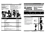
Hydraulically-Driven Pressure Washers
Model
Max.
Max.
Estimated
Number
GPM
PSI
GPM
PSI
Description
Weight Ea.
Hydraulic Motor
Requirements
1802C
3.0
1000
5.0
1300
Forged Brass Head Triplex Pump
38 lbs.
with hydraulic motor, adjustable unloader,
gauge,
1
⁄
2
"
NPT input,
3
⁄
8
"
quick disconnect output,
and 50 ft. hose and gun assembly
1804C
3.0
1500
8.0
1900
Forged Brass Head Triplex Pumps with hydraulic
41 lbs.
1806C
3.0
2000
11.0
1300
motor, chemical injector, adjustable unloader,
26 lbs.
1824C
4.0
1500
8.5
2000
gauge
3
⁄
4
"
GH input,
3
⁄
8
"
quick disconnect output,
49 lbs.
1826C
4.0
2000
8.5
2000
and 50 ft. hose and gun assembly
49 lbs.
Hydraulically-Driven Pressure Washers with Hose and Gun Assembly
Model
Max.
Max.
Estimated
Number
GPM
PSI
GPM
PSI
Description
Weight Ea.
Hydraulic Motor
Requirements
Installation, Operation, Repair, and Parts Manual
02/08
Description