


Issue Date: 4.30.22
Manual P/N
117471 rev. -
For machines beginning with S/N D22042134 and above
LISTED
2674 N. Service Road, Jordan Station
Ontario, Canada L0R 1S0
(905) 562-4195 Fax: (905) 562-4618
Toll-free: 1( 800) 263-5798
3765 Champion Boulevard
Winston-Salem, NC 27105
(336) 661-1556 Fax: (336) 661-1660
Toll-free: 1 (800) 858-4477
Printed in the USA
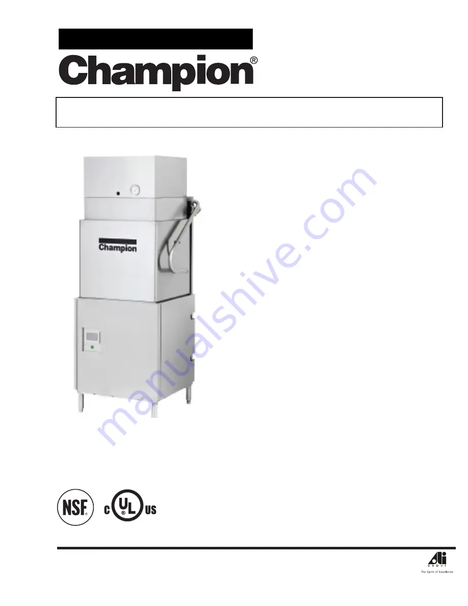
Installation Manual
Tall hot water sanitizing machine w/fresh
water rinse and built-in stainless steel
electric booster, Optional Ventless Heat Recovery
Standard height h
ot water sanitizing machine w/
fresh water rinse and built-in stainless steel
electric booster, Optional Ventless Heat Recovery
Models:
DH6000T-VHR
DH6000T
DH6000-VHR
DH6000
DH6000T-VHR
M2 SERIES


