6
1. Check the converyor drive motor to ensure it rotates in the correct direction. The motor
shaft must rotate in a counterclockwise direction when viewed from the rear.
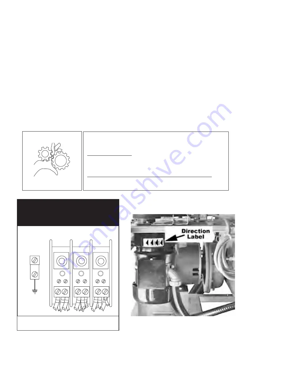
2. The dishwasher motors are phased together; therefore, if the conveyor motor rotation
is correct then the pumo motors will also be correct.
3. If the conveyor motor rotation is not correct, then reverse the L1 and L2 wires on the
out put side of the dishwasher main ternimal block located inside the top-mounted
control cabinet. Check to ensure the conveyor motor rotates counterclockwise after
reversing the wires.
NOTE:
The prewash, wash and rinse pump motor shafts rotate clockwise when viewed from the
rear. In addition, the motors have direction arrow labels indicating the properrotations.
Installation
Electrical Connections
(continued)
Motor Rotation
THREE PHASE
POWER CONNECTION
LINE IN
L1
L2
L3
GRD
Main Terminal Block Inside the Top-mounted Control
Cabinet.
WARNING:
Moving Conveyor Parts may cause INJURY OR DEATH.
Keep hands and clothing clear of the conveyor when the
conveyor is moving.
USE EXTREME CAUTION WHEN THE CONVEYOR IS MOVING.
Motor Direction Rotation Label on Motor Frame.
Summary of Contents for 106 PW
Page 22: ...14 Installation Removing the Spray Arm End Plugs Installing the Lower Spray Arm Assembly ...
Page 23: ...15 Installation Installing the Upper Spray Arm Assembly Removing the Spray Arm End Plugs ...
Page 25: ...17 Installing the Dual Rinse DR scrap screens Installation ...
Page 29: ...21 Blank Page This Page Intentionally Left Blank ...
Page 52: ...11 3 5 6 7 2 1 3 3 13 12 8 9 10 4 14 3 Prewash Panels and Curtains L R Direction Shown 44 ...
Page 56: ...Two Tank Panels and Curtains 8 7 16 5 3 1 6 2 5 1 2 3 4 15 15 11 10 9 14 13 12 48 ...
Page 58: ...1 15 2 3 16 4 5 17 18 7 6 8 9 10 14 13 12 11 11 13 7 Drive Motor Assembly 50 ...
Page 68: ...2 1 Prewash Scrap Screens 60 ...
Page 82: ...Dual Rinse DR Pump Motor Assembly 1 2 3 4 5 6 7 Not Available as a separate repair part 74 ...
Page 84: ...1 2 9 6 7 5 A 3 4 5 Suction Discharge L R Application Shown Prewash Pump Suction Discharge 76 ...
Page 86: ...Wash Power Rinse Pump Suction Discharge 1 2 3 5 6 A B 4 Tank 78 ...
Page 88: ...8 1 18 4 15 2 14 9 10 17 20 12 7 6 5 11 21 13 3 16 19 2 Pump Motor Assembly 80 ...
Page 90: ...Float Switches 5 2 4 3 3 1 Prewash Single Tank Two Tank 82 ...
Page 92: ...1 2 3 4 3 5 6 Single Tank Electric Wash Tank Heat 84 ...
Page 94: ...3 A 2 Tank 2 1 Wash Rinse Two Tank Electric Wash Tand RInse Tank Heat 86 ...
Page 96: ...Thermostats and Thermistors Single Tank High Limit Control Two Tank 4 Tank 1 2 3 3 88 ...
Page 114: ...10 11 8 9 8 7 6 5 4 5 1 2 3 2 2 1 Two Tank Steam Heat with K2 Steam Booster 106 ...
Page 116: ...1 Tank 2 3 7 4 5 6 8 Single Tank Steam Heat 108 ...
Page 118: ...1 3 4 5 6 2 3 7 Tank Tank 8 9 10 Two Tank Steam Heat 110 ...
Page 132: ...2 1 5 3 4 Not a Part of Item 3 must order separately Final Rinse Drain Assembly 124 ...
Page 140: ...6 7 8 A 2 4 2 5 2 5 4 2 3 1 Extended Vent Cowls and Splash Shields 132 ...
Page 142: ...8 7 2 2 5 5 2 2 3 6 4 4 1 Standard Vent Cowls 134 ...
Page 144: ...1 2 3 4 5 6 7 8 9 10 11 12 13 14 15 16 17 5 7 11 Single Tank Hot Water Coil HWC Heat 136 ...
Page 148: ...24 Sideloader 1 2 7 8 9 10 11 3 4 5 6 140 ...
Page 150: ...30 Sideloader 1 2 7 8 9 10 11 3 4 5 6 142 ...
Page 152: ...1 2 Dish racks 144 ...
Page 154: ...This Page Intentionally Left Blank Blank Page 146 ...
Page 156: ...148 Single Tank Electric Steam ...
Page 157: ...149 Single Tank Electric Steam Hot Water Coil ...
Page 158: ...150 Two Tank Electric Steam ...
Page 159: ...151 Two Tank Electric Steam Hot Water Coil ...
Page 160: ...152 12KW and 22KW Single Tank Electric Booster ...
Page 161: ...153 15KW and 24KW Two Tank Electric Booster ...
Page 162: ...154 30KW Heat Recovery Electric Booster ...
Page 163: ...155 Thermistor Connections ...
Page 164: ...156 90 180 Rack Advance Connections ...
Page 165: ...Circuit Board Diagnostics Solid State Circuit Board P N 114756 Circuit Board Diagnostics 157 ...


