Champion Power Equipment 71531 Owner'S Manual & Operating Instructions Download Page 19

REV 71531-20140505  

16

71531


ENGLISH

OPERATION

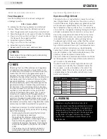
Never exceed the specified capacity when adding 
loads to the generator.

NOTE

Operation using the alternative main jet at 
elevations lower than the recommended minimum 
altitude can damage the engine. For operation at 
lower elevations, the standard main jet must be 
used. Operating the engine with the wrong engine 
configuration at a given altitude may increase 
its emissions and decrease fuel efficiency and 
performance.

WARNING

Carburetor 

Code 

Main Jet

Part Number

Altitude

P28-3-Z

Standard

47.131017.21.Z

5500 Feet
(1676 Meters)

Altitude

47.131017.21.01.Z

P28-3-H

Standard

47.131017.21.H

Altitude

47.131017.21.01.H

P28-3-Y

Standard

47.131017.21.Y

Altitude

47.131017.21.01.Y

Do Not Overload Generator Cont’d.

Operation at High Altitude Cont’d.

NOTE

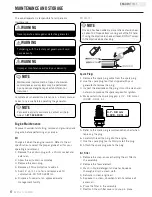
Observing frost on LPG containers and regulators 

is common during operation and normally is not 

an indication of a problem. As LPG vaporizes and 

travels from the tank to the generator engine it 

expands. The amount of frost that forms can be 

affected by the size of the container, the amount of 

fuel being used, the humidity of the air and other 

operating conditions. In unusual situations this 

frost may eventually restrict the flow of gas to the 

generator resulting in deteriorating performance. 

For example, if the tank temperature is reduced 

to a very low level then the rate at which the LPG 

vaporizes is also reduced and may not provide 

sufficient fuel flow to the engine. This is not an 

indication of a problem with the generator but 

only a problem with the flow of gas from the LPG 

container. If generator performance seems to be 

deteriorating at the same time that ice formation is 

observed on tank valve, hose or regulator then some 

actions may be taken to eliminate this symptom.


In these rare situations it can be helpful to reduce 

or eliminate the cold fuel system effects by doing 

one of the following:


– Exchanging fuel tanks to allow the first tank to 

warm up, repeating as necessary


– Placing the LPG container at the end of the 

generator near the handle, where engine fan air 

flows out from the generator. This air is slightly 

heated by flowing over the engine. The container 

should not be placed in the path of the muffler 

outlet.


– The container can be temporarily warmed by 

pouring warm water over the top of the tank.

Operation at High Altitude

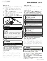
The density of air at high altitude is lower than at sea 
level. Engine power is reduced as the air mass and air-
fuel ratio decrease. Engine power and generator output 
will be reduced approximately 3½% for every 1000 
feet of elevation above sea level. This is a natural trend 
and cannot be changed by adjusting the engine. At high 
altitudes increased exhaust emissions can also result 
due to the increased enrichment of the air fuel ratio. 
Other high altitude issues can include hard starting, 
increased fuel consumption and spark plug fouling.
To alleviate high altitude issues other than the natural 
power loss, Champion Power Equipment can provide a 
high altitude carburetor main jet. The alternative main 
jet and installation instructions can be obtained by 
contacting Customer Support. Installation instructions 
are also available in the Technical Bulletin area of the 
Champion Power Equipment internet site.
The part number and recommended minimum altitude 
for the application of the high altitude carburetor main 
jet is listed in the table below.
In order to select the correct high altitude main jet 
it is necessary to identify the carburetor model. For 
this purpose, a code is stamped on the side of the 
carburetor. Select the correct main jet part number 
corresponding to the carburetor code found on your 
particular carburetor.

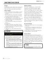
Power Management

Use the following formula to convert voltage and 
amperage to watts:

Volts x Amps = Watts

To prolong the life of your generator and attached 
devices, follow these steps to add electrical load:
1.  Start the generator with no electrical load attached
2.  Allow the engine to run for several minutes to stabilize.
3.  Plug in and turn on the first item. It is best to attach 

the item with the largest load first.

4.  Allow the engine to stabilize.
5.  Plug in and turn on the next item.
6.  Allow the engine to stabilize.
7.  Repeat steps 5-6 for each additional item.

Summary of Contents for 71531

Page 1: ...338 0999 www championpowerequipment com 8400 Starting Watts 6750 Rated Watts LPG 9375 Starting Watts 7500 Rated Watts Gas DUAL FUEL GENERATOR SAVE THESE INSTRUCTIONS Important Safety Instructions are...

Page 2: ...r Champion Power Equipment product is designed and rated for continuous operation at ambient temperatures up to 40 C 104 F When your product is needed your product may be operated at temperatures rang...

Page 3: ...ad Generator 15 Capacity 15 Power Management 16 Operation at High Altitude 16 Maintenance and Storage 17 Engine Maintenance 17 Oil 17 Spark Plugs 17 Air Filter 17 Spark Arrester 18 Cleaning 18 Adjustm...

Page 4: ...this information available when ordering parts and when making technical or warranty inquiries Accessories Champion Power Equipment manufactures and sells accessories designed to help you get the most...

Page 5: ...hazardous situation which if not avoided may result in minor or moderate injury CAUTION CAUTION used without the safety alert symbol indicates a potentially hazardous situation which if not avoided m...

Page 6: ...amaged or frayed DO NOT operate generator in wet weather DO NOT allow children or unqualified persons to operate or service the generator Use a ground fault circuit interrupter GFCI in damp areas and...

Page 7: ...generator s running capacity can damage the generator and or electrical devices connected to it DO NOT overload the generator Start the generator and allow the engine to stabilize before connecting el...

Page 8: ...FLAMMABLE AND EXPLOSIVE Fire or explosion can cause severe burns or death Unintentional startup can result in entanglement traumatic amputation or laceration DANGER When adding or removing Gas Turn th...

Page 9: ...l Tank 6 1 gallon 23 L capacity fuel tank 2 Choke Used to start the engine 3 Air Cleaner Protects the engine by filtering dust and debris from the intake air 4 Recoil Starter Used to manually start th...

Page 10: ...al Consult an electrician for local grounding regulations 7 120 Volt AC 30 Amp Twist Lock Receptacle NEMA L5 30R May be used to supply electrical power for the operation of 120 Volt AC 30 Amp single p...

Page 11: ...nge Bolt M10x120 for Wheel 2 Bushing 2 Flat Washer 10 2 Lock Nut M10 2 Support Leg w Vibration Mounts 1 Flange Bolt M8x16 for Support Leg 2 Flange Lock Nut M8 2 Other Oil 1 2 qt 1 1 L LPG Hose With Re...

Page 12: ...lowing tools to install the wheels 17 mm wrench OR adjustable wrench not included Socket wrench with a 16 mm socket not included Pliers not included 1 Before adding fuel and oil tip the generator on i...

Page 13: ...evel in the crankcase falls below the threshold level CAUTION Add Engine Oil DO NOT attempt to crank or start the engine before it has been properly filled with the recommended type and amount of oil...

Page 14: ...an ethanol content of less than 10 by volume 2 DO NOT mix oil with fuel 3 Clean the area around the fuel cap 4 Remove the fuel cap 5 Slowly add fuel to the tank DO NOT OVERFILL Fuel can expand after...

Page 15: ...hat have not been plugged or kept closed must also be purged The purging process should be done by a LPG supplier Cylinders from an exchange supplier should have been purged and filled properly alread...

Page 16: ...when positioning generator Failure to follow proper safety precautions may void manufacturer s warranty Do not operate or store the generator in rain snow or wet weather Using a generator or electrica...

Page 17: ...attery switch to the ON position 7 ELECTRIC START Press and hold the ignition switch to the START position Release as the engine begins to roll over If the engine fails to start within five seconds re...

Page 18: ...ne This usually takes a few minutes 5 Press the engine switch to the OFF position 6 Turn Battery Switch to the Off Position Important Always ensure that the Fuel Valve and the Engine Switch are in the...

Page 19: ...end of the generator near the handle where engine fan air flows out from the generator This air is slightly heated by flowing over the engine The container should not be placed in the path of the muf...

Page 20: ...lug 6 Carefully thread the plug into the engine 7 Use the spark plug tool to firmly install the plug 8 Attach the spark plug wire to the plug For service or parts assistance contact our help line at 1...

Page 21: ...tenance and Storage Federal and local laws and administrative requirements indicate when and where spark arresters are required When ordered spark arresters are required for operation of this generato...

Page 22: ...ulling the engine recoil cord If the battery voltage is extremely low the charging circuit may not be able to re charge the battery In this case the battery must be connected to a standard automotive...

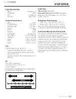
Page 23: ...F6RTC Replacement spark plug NGK BPR6ES or equivalent Make certain the spark plug gap is 0 7 0 8 mm or 0 028 0 031 in An Important Message About Temperature Your Champion Power Equipment product is de...

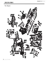
Page 24: ...56 57 66 23 82 83 84 85 86 87 88 44 65 1 2 4 5 6 7 8 9 10 11 12 13 14 15 16 17 18 19 20 21 5 5 16 59 62 63 64 60 61 67 68 69 70 71 72 73 74 75 76 77 78 79 80 81 76 89 90 91 92 93 95 97 98 99 94 100 10...

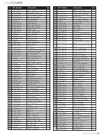
Page 25: ...00800 09 2 Decorative Plate 1 68 152 070031 00 Jacket LPG Hose 3 69 6 5 233 420 2 Frame 1 70 1 6177 1 10 Flange Lock Nut M10 4 Part Number Description Qty 71 152 201200 03 Motor Mount I 2 72 1 6182 10...

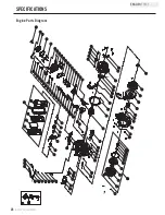
Page 26: ...108 85 10 1 2 3 4 5 6 7 8 9 11 12 13 14 15 16 17 18 19 20 16 24 25 26 27 28 29 30 31 33 34 35 12 36 30 37 38 23 39 41 42 43 44 46 47 48 49 50 51 52 53 12 54 55 57 58 59 60 61 62 65 66 68 69 70 71 72 7...

Page 27: ...1 56 2 01 010 Stud Bolt M8 35 2 57 2 15 002 F6RTC Spark Plug F6RTC 1 Part Number Description Qty 58 2 08 014 Flange Bolt M10 80 4 59 46 020002 00 Gasket Cylinder Head Cover 1 60 47 021000 00 Cylinder...

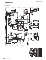
Page 28: ...DCW multi purpose meter FUEL CUT SOLENOIL B G B G W G W G G OFF G Y G Y G Y 3 4 5 2 1 6 G Y Charger Br G Y SWITCH lb l la G Y EARTH TERMINAL G Y G Y L14 30R L5 30R 5 20R B W W R R R G Y B B W G Y W W...

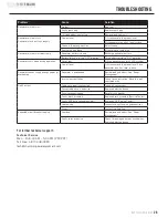
Page 29: ...position Generator shuts down during operation Out of fuel Fill the gasoline tank or fill LPG cylinder Low oil level Fill crankcase to the proper level Place generator on a flat level surface Generato...

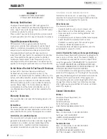
Page 30: ...nd or labor if this generator is deemed to have been misused neglected involved in an accident abused loaded beyond the generator s limits modified installed improperly or connected incorrectly to any...

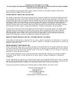
Page 31: ...parts and labor For engines less than or equal to 80cc only the fuel tank and fuel line is subject to the evaporative emission control warranty requirements of this section MANUFACTURER S EMISSION CON...

Page 32: ...be warranted for the period of time prior to the first scheduled replacement point for that part If the part fails prior to the first scheduled replacement the part shall be repaired or replaced by CP...

Page 33: ...ets Carburetor Purge Port Connector TO OBTAIN WARRANTY SERVICE You must take your CPE engine or the product on which it is installed along with your warranty registration card or other proof of origin...

Reviews: