background image

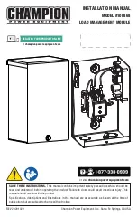
INSTALLATION MANUAL

MODEL #100868

LOAD MANAgEMENT MODULE

REV 20201029

Champion Power Equipment, Inc., Santa Fe Springs, CA USA

or visit 

championpowerequipment.com

SAVE THESE INSTRUCTIONS.

 This manual contains important safety precautions which should be 

read and understood before operating the product. Failure to do so could result in serious injury. This 
manual should remain with the product.
Specifications, descriptions and illustrations in this manual are as accurate as known at the time of 
publication, but are subject to change without notice.

REGISTER YOUR PRODUCT ONLINE

at 

championpowerequipment.com

Summary of Contents for 100868

Page 1: ...ns important safety precautions which should be read and understood before operating the product Failure to do so could result in serious injury This manual should remain with the product Specificatio...

Page 2: ...y Instructions 4 Safety and Dataplate Labels 6 Safety Symbols 6 Controls and Features 7 Electrical Installation Diagram 8 Installation 9 Unpacking 9 Installing the Load Management Module LMM 9 Connect...

Page 3: ...rt has been made to ensure the accuracy and completeness of the information in this manual at the time of publication and we reserve the right to change alter and or improve the product and this docum...

Page 4: ...bligation or liability whatsoever The manufacturer cannot anticipate every possible circumstance that might involve a hazard The warnings in this manual tags and decals affixed to the unit are therefo...

Page 5: ...tor manual section to locate aXis ENGINE CONTROL module lock out procedure CAUTION Consult with your Local municipal State and National electrical codes for proper mandatory wiring methods NOTICE Impr...

Page 6: ...l entretien DANGER PELIGRO DANGER K 485 Colors LPN 1973 L SF Rev A Size 50 x 25mm Artwork Notes dius 2mm safe margin to be printed trate Revision Changes to Champion Power Equipment The contents are...

Page 7: ...remote LMM turns power on and off to the load by using a Power Line Carrier PLC signal The unit is capable of controlling resistive loads up to 50 Amps when wired into the load circuit The load shoul...

Page 8: ...100868 Load Management Module Controls and Features 8 Electrical Installation Diagram HOME PANEL METER GENERATOR UTILITY LOAD MANAGEMENT MODULE AIR CONDITIONER ATS 200 50...

Page 9: ...nduit Pliers Fittings Wire stripper Twist on wire connectors as needed Installing the Load Management Module LMM The enclosure is NEMA type 3R rated and is suitable for indoor outdoor installations Ge...

Page 10: ...nd L2 Line to the top of the contactor relay LINE connections 4 Connect the L1 and L2 lines to the bottom of the contactor relay LOAD connections 5 Connect the ground to the ground terminal 6 Max Torq...

Page 11: ...are the designated ON or OFF position settings for the DIP switches DIP Switches 1 3 on LMM circuit board are used to communicate with the ATS circuit board and create a hierarchy Switches 1 2 are us...

Page 12: ...utage 6 Return UTILITY circuit breaker to the ON position ATS will transfer load back to utility and generator will cool down and shut off 7 Repeat this process if LMM units are added or removed from...

Page 13: ...ONS Unit Enclosure type NEMA 3R indoor outdoor Amperage 50A resistive Nominal Voltage 240VAC Height 8 2 in 208 mm Width 5 2 in 133 mm Depth 3 8 in 97 mm Torque Neutral Bar 18 10 AWG Cu9Al 35 in lb 14...

Page 14: ...he life of a part or the equipment as a whole Installation Use and Maintenance This warranty will not apply to parts and or labor if the product is deemed to have been misused neglected involved in an...

Reviews: