CHA F-LOOP 3.0
Page
9
u.
3/8” Antenna Mount
-
The 3/8” Antenna Mount is an unthreaded hole at the r
ear of the
Aluminum Base Plate (n) that enables attachment of the CHA F-LOOP 3.0 to any
3/8”
antenna
mount using a 3/8” x 24
hex bolt.
v.
Duffel Bag
–
The military-style Duffel Bag
(not shown)
, is included with all models and is used to
store the components of the CHA F-LOOP 3.0 when not deployed. It is incredibly versatile and
can also be used as a backpack.
Standard Single Flexible Loop Assembly (CHA F-LOOP 3.0 BASIC)
The Standard Single Flexible Loop configuration uses the standard Flexible Radiator Loop (b) and small
Coupling Loop (c) included with the CHA F-LOOP 3.0 BASIC, CHA FLOOP 3.0 PLUS, and CHA F-FLOOP 3.0
TOTAL antennas.
The CHA F-LOOP 3.0 BASIC antenna should be installed near the radio set; either indoors or in a sheltered
outside area, such as a balcony or porch. Because the magnetic component of an electromagnetic wave
is maximum at the boundary between the ground and the space above, loop performance is usually best
when the loop is located near the gr
ound at a distance outside of the loop’s close
-in induction field (just
a loop diameter or two). The CHA F-LOOP 3.0 BASIC is not waterproof and must be installed in an area
protected from the weather. Do not use an antenna tuner or coupler with this antenna, as it may cause
you to mistune the antenna.
Perform the following steps to assemble the Standard Single Flexible Loop configuration.
1.
Select a location to setup the CHA F-LOOP
3.0 BASIC antenna. The location can be
indoors or in an outdoors area protected
from the weather. The location must
facilitate accessibility by the operator to the
Tuning Knob (h). The operator needs to be
able to adjust the Tuning Knob while
listening to the receiver, activating the
transmitter, and observing the SWR meter.
If used indoors, the location should also be
reasonably away from switching power
supplies, Internet routers, and other sources
of electrical and electronic interference.
2.
Remove the CHA F-LOOP 3.0 BASIC
components from the Duffel Bag (v).
3.
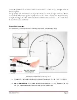
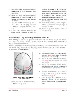
Attach the Telescoping Mast (g) to the
Tuning Unit (a) by screwing the bottom of
the Telescoping Mast onto the Telescoping
Mast Stud (q), located on the top of the
Tuning Unit. Tighten snuggly, by gripping the
base of the Telescoping Mast and turning
clockwise. Do not grip the mast tubing or
use tools when tightening.
4.
Attach the small 6 ½ inch Coupling Loop (c)
to the Coupling Loop Attachment (j), located
at the top of the Telescoping Mast, by
placing the threaded hole in the Coupling
Loop bracket over the Coupling Loop
Attachment stud and turning the Coupling
Loop Adjustment (k) knob until snug. The
UHF connector should be in front of the
Telescoping Mast and point down, as shown
in the upper-left inset of Plate (3).
5.
Extend the Telescoping Mast sections so that
the Telescoping Mast is 24 inches in length.
6.
Connect one end of the Flexible Radiator
Loop (b) to the left Radiator Loop
Connection (f).


