CHA F-LOOP 3.0
Page
7
c.
Coupling Loop -
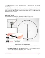
The Coupling Loop is a 6 1/2 inch diameter rigid aluminum loop, which is
attached to the end of the Telescoping Mast (g) and used in the CHA F-LOOP BASIC 3.0 and CHA
F-LOOP 3.0 PLUS antenna configurations. A larger, 8 inch diameter rigid aluminum loop, is used
in conjunction with the Booster Flexible Loop (e) in the CHA F-LOOP 3.0 TOTAL antenna
configuration.
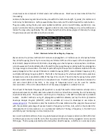
Plate 4. CHA F-LOOP 3.0 Tuning Unit Details.
d.
Flexible Radiator Loop Extension -
The Flexible Radiator Loop Extension consists of a 102 inch
length of shorted coaxial cable with UHF Plugs at both ends. The Flexible Radiator Loop
Extension enables the CHA F-LOOP 3.0 BASIC to operate the 80 meter ham band.
e.
Flexible Booster Loop
(included with TOTAL model) -
The Flexible Booster Loop consists of a 48
inch diameter / 146 inch length of shorted coaxial cable with UHF Plugs at both ends and is
designed to increase CHA F-LOOP 3.0 TOTAL performance in the 60 through 15 meter ham
bands.
f.
Flexible Radiator Loop Connections -
The Flexible Radiator Loop Connections are UHF sockets
(SO-239) located on the right and left sides of the Tuning Unit (a).
g.
Telescoping Mast -
The Telescoping Mast attaches the Tuning Unit (a) to the Coupling Loop (c).
h.
Tuning Knob -
The Tuning Knob is located on the front of the Tuning Unit (a) and is used to adjust
the resonant frequency of the loop. The tuning capacitor rotates a total of around 2 ¾
revolutions. Left, or counter-clockwise, increases the resonant frequency of the antenna. Right,
or clockwise, decreases the resonant frequency of the antenna.
i.
Band Switch -
The Band Switch is located on the top of the Tuning Unit (a). It has two positions,
marked
“A” and “B”.
“A” is the Low Range and “B” is the High Range. See the section “Loop
Operation” for more details
on operation of the Band Switch.


