


CONTENTS OF THE CARTON
(1) Sliding gate actuator unit
(2) Base Plate
(3) Installation accessories pack
Hinge pins with circlips (2)
Emergency opening handle (1)
Capacitor (1)
(4) Instruction manual
PRODUCT DESCRIPTION
For SGO500, the maximum gate width may not exceed 6 m.
The maximum weight may not exceed 600 kg.
For design reasons, all sliding gate actuator units, operating
with a linear movement, must follow the given installation
dimensions.
Technical data
Power supply
230V/50 Hz
Current Rating
1,5 A
Power
350 Watt
Capacitor
10 mF
Cycles/Hr.-max
20
Speed
12m/min.
Max. width of gate
6 m
Max. weight of gate
600 kg
Motor thermal overload switch
140° C
IP Rating Motor
IP 54
Rated weight
10 kg
Dimensions
refer to Illustration 2
INSTALLATION -
PREPARATIONS
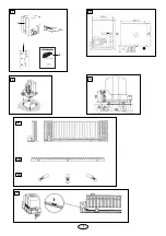
Before installation, please check contents of packaging.
Please refer to Illustration 1.
Ensure your gate equipment functions correctly. The gate
must move smoothly without jerking and must not stick at
any point. Take into account the fact that the ground level
may raise by several centimetres in the winter.
To avoid undesirable jerking movement, the gate should be
stable and should have as little play as possible. The easier
the gate movement, the finer the torque adjustment.
PROCEDURE:
♦
ASSEMBLY OVERVIEW
The assembly process is shown in Illustration 3 - 5. The
drive must be mounted behind the wall, so that no part of it is
visible in the gate opening (Illustraion 5A). The motor is
mounted on the embedded base plate (Illustration 4). The
toothed rack shown in Illustration 5B should be mounted on
the gate with the aid of the mounting bolts (Illustration 5C).
♦
ASSEMBLY DIMENSIONS
Determine the appropriate height for mounting the toothed
rack on the gate, and determine the assembly dimensions for
the motor unit and base plate with reference to Illustration 4.
If the gate design is unsuitable for direct mounting of the
toothed rack, a mounting support (angular steel section,
moulded tube, etc.) must be mounted first.
1
2
2
3
6
INHALT DES KARTONS
(1) Schiebetorantrieb
(2) Bodenplatte
(3) Montagezubehörbeutel
Befestigungsbolzen mit Sicherheitsringen (2)
Notentriegelung (1)
Kondensator (1)
(4) Montageanleitung
PRODUKT BESCHREIBUNG
Beim SGO500 darf die Torbreite 6 m nicht übersteigen.
Das maximale Gewicht darf 600 kg nicht übersteigen.
Bauartbedingt müssen bei allen Schiebetorantrieben, die mit
linearer Bewegung arbeiten, bestimmte Einbaumße
eingehalten werden.
Technische Daten
Netzanschluß
230V/50 Hz
Stromaufnahme
1,5 A
Leistungsaufnahme
350 Watt
Kondensator
10 mF
Öffnungszyklen
20
Torblattgeschwindigkeit
12m/min.
Max. Torbreite
6 m
Max. Torgewicht
600 kg
Motorthermoschutz
140° C
Schutzgrad Motor
IP 54
Nettogewicht
10 kg
Abmessungen
siehe Abb. 2
INSTALLATION -
VORBEREITUNGEN
Überprüfen Sie bitte vor der Montage den Inhalt der
Verkaufsverpackung auf Vollständigkeit. Siehe Abbildung 1.
Stellen Sie die einwandfreie Arbeitsweise Ihrer Torvorrichtung
sicher. Das Tor muß gleichmäßig und stoßfrei laufen, es darf
an keiner Stelle hängenbleiben. Denken Sie daran, daß sich
der Boden im Winter um einige Zentimeter heben kann.
Um störende Pendelbewegungen zu vermeiden sollte das Tor
stabil und möglichst spielfrei sein. Je leichtgängiger der
Flügel, desto feinfühliger ist die Kraft einzustellen.
VORGEHENSWEISE:
♦
MONTAGEÜBERSICHT
Eine Montageübersicht zeigen die Abbildungen 3 bis 5. Der
Antrieb muß hinter der Mauer so angebracht werden, daß
kein Teil in die Toröffnung hereinragt (Abb. 5a). Auf die
eingelassene Grundplatte (Abb 4) wird der Motor montiert.
Die in Abb. 5b gezeigte Zahnstange ist mit Hilfe der
Befestigungsbolzen (Abb. 5c) am Tor zu befestigen.
♦
MONTAGEMAßE
Stellen Sie fest, in welcher Höhe am Tor die Zahnstange am
geeignetsten anzubringen ist und ermitteln Sie anhand der
Abbildung 4 die Montagemaße für Motoreinheit und
Grundplatte. Wenn die Torkonstruktion zum Befestigen der
Zahnstange nicht geeignet ist, muß ein Befestigungsprofil
(Winkeleisen, Formrohr etc.) montiert werden.
1
2
3
6
D
GB


