background image

Having a Problem? 

(continued)

Situation

Probable Cause & Solution

The opener strains
or maximum force is
needed to operate
the door:

The door may be out of balance or the springs are broken. Close the door and use the
manual release rope and handle to disconnect the trolley. Open and close the door
manually. A properly balanced door will stay in any point of travel while being supported
entirely by its springs. If it does not, disconnect the opener and call for professional
garage door service. 

Do not increase the force to operate the opener.

The opener motor
hums briefly, then
won't work:

1. The garage door springs are broken. See above.

2. If the problem occurs on the first operation of the opener, door may be locked.

Disable the door lockIf the belt was removed and reinstalled, the motor may be out
of phase. Remove the belt; cycle the motor to the down position. Observe the drive
sprocket. When it turns in a clockwise direction and stops in the down position,
reinstall the belt.

Repeat the safety reverse test after the adjustment is complete.

The opener won't
operate due to
power failure:

1. Use the manual release handle to disconnect the trolley. The door can be opened

and closed manually. When the power is restored, press the Door Control push bar
and trolley will automatically reconnect (unless trolley is in the lockout position,
see page 32).

2. The Outside Quick Release accessory (for use on garages with no service door)

disconnects the trolley from outside the garage in case of power failure.

35

The door reverses
for no apparent
reason and opener
lights don't blink:

1. Is something obstructing the door? Pull the manual release handle. Operate the door

manually. If it is unbalanced or binding, call for professional garage door service.

2. Clear any ice or snow from the garage floor area where the door closes.

3. Review the force adjustment procedures on page 29.

4. If door reverses in the 

fully closed position, decrease the travel limits (page 28).

Repeat the safety reverse test after adjustments to force or travel limits. The need
for occasional adjustment of the force and limit settings is normal. Weather
conditions in particular can affect door travel.

The opener lights…

The door reverses for
no apparent reason
and opener lights
blink for 5 seconds
after reversing:

don't turn on:

Replace the light bulbs (75 watts maximum). Use a 

standard neck garage door opener

bulb if regular bulb burns out.

don't turn off:

Is the Light feature 

on? Turn it off.

Check the safety reversing sensor. Remove the obstruction or align the receiving eye.
See page 23.

The door opens but
won't close:

1. If the opener lights blink, check the safety reversing sensor. See page 23

2. If the opener lights do not blink and it is a new installation, check the down force.

See Adjustment Step 2, page 29. For an existing installation, see below.

Repeat the safety reverse test after the adjustment is complete.

Summary of Contents for Security+ 9500-3K

Page 1: ...r WILL NOT CLOSE unless the Protector System is connected and properly aligned Periodic checks of the opener are required to ensure safe operation The model number label is located under the light len...

Page 2: ...trolley sectional door 26 Connect door arm to trolley one piece door 27 Adjustment section pages 28 30 Travel limit adjustments 28 Force adjustments 29 Test the Protector System 30 Test the safety rev...

Page 3: ...Do not try to loosen move or adjust them yourself Ropes left on a garage door could cause someone to become entangled and killed Remove all ropes connected to the door before installing and operating...

Page 4: ...pon garage construction extension brackets see Accessories or wood blocks may be needed to fasten sensors to mounting locations Step 10 page 22 Floor mounting of the safety reversing sensor will requi...

Page 5: ...reversing sensor page 21 Depending on garage construction extension brackets see Accessories or wood blocks may be needed to fasten sensors to mounting locations Step 10 page 22 Floor mounting of the...

Page 6: ...racket SECURITY Multi Function Remote Control Transmitter 2 LOCK LIGHT SECURITY Mini Remote Control Safety Labels and Literature 2 Safety Reversing Sensors 1 Sending Eye and 1 Receiving Eye with 2 Con...

Page 7: ...16 18x2 1 2 2 Carriage Bolt 1 4 20x1 2 12 Master Link 2 Ring Fastener 3 Trolley Threaded Shaft 1 Lock Washer 5 16 6 Lag Screw 5 16 9x1 5 8 2 SAFETY REVERSING SENSOR Wing Nut 2 Insulated Staples 20 RA...

Page 8: ...ucted to do so Assembly Section Pages 8 11 When tightening the screws be sure to keep bracket parallel to the rail Otherwise the rail may bow when the opener is operated Right Wrong Align the 4 T rail...

Page 9: ...5 16 18x1 2 washered screws mounted in the top of the opener Align the holes in the back section of the T rail with the holes in the opener Fasten the rail with the 2 washered screws previously remove...

Page 10: ...eth must engage the belt Figure 2 Use the second master link to connect the belt to the flat end of the trolley threaded shaft Figure 1 Check to make sure the belt is not twisted Remove the screwdrive...

Page 11: ...structed to do so 6 Locate the Door Control within sight of the door at a minimum height of 5 feet where small children cannot reach and away from all moving parts of the door 7 Install the User Safet...

Page 12: ...rance is minimal It may be mounted on the wall upside down if necessary to gain approximately 1 2 If you need to install the header bracket on a 2x4 on wall or ceiling use lag screws not supplied to s...

Page 13: ...acket height on header wall 12 Measure UP from top of CLOSED door Proceed to Step 2 page 14 13 Header Wall Highest Point of Travel Door Distance Jamb Hardware Door Highest Point of Travel Header Wall...

Page 14: ...use the holes designated for ceiling mount Drill 3 16 pilot holes and fasten the bracket securely to a structural support with the hardware provided Fasten the Header Bracket to the Ceiling Installat...

Page 15: ...e garage floor below the header bracket Use packing material as a protective base If the door spring is in the way you ll need help Have someone hold the opener securely on a temporary support to allo...

Page 16: ...T rail If the top panel hits the trolley when you raise the door pull down on the trolley release arm to disconnect the inner and outer sections The trolley can remain disconnected until Step 12 is c...

Page 17: ...ke sure the T rail is centered over the door or in line with the header bracket if the bracket is not centered above the door Remove the 2x4 Operate the door manually If the door hits the rail raise t...

Page 18: ...ort 4 Connect the bell wire to the terminal screws on the opener panel white to 2 white red to 1 5 After testing replace the cover by inserting top tabs and snapping into place Note After installation...

Page 19: ...ors are heavy If the door is open when the handle is pulled the door could close inadvertently if it is not properly balanced Serious injury may result to persons under the door Make sure the doorway...

Page 20: ...Black Wire To make a permanent connection through the 7 8 diameter hole in the top of the opener according to local code Remove the opener cover screws and set the cover aside Remove the attached 3 p...

Page 21: ...cator light transmits an invisible light beam to the receiving eye with a green indicator light If an obstruction breaks the light beam while the door is closing the door will stop and reverse to full...

Page 22: ...curved arms facing the door Snap into place against the side of the track It should lie flush with the lip hugging the back edge of the track as shown in Figure 2 If your door track will not support t...

Page 23: ...rrect The sending eye orange indicator light will glow regardless of alignment or obstruction If the green indicator light in the receiving eye is off dim or flickering and the invisible light beam pa...

Page 24: ...the bracket Position the bracket on the face of the door within the following limits A The top edge of the bracket 2 4 below the top edge of the door B The top edge of the bracket directly below any s...

Page 25: ...edure Center the bracket on the top of the door in line with the header bracket as shown Mark holes Drill 5 16 pilot holes and fasten the door bracket with hardware provided If the door has no exposed...

Page 26: ...n sections Select holes as far apart as possible to increase door arm rigidity Figure 3 If holes in curved arm are above holes in straight arm disconnect straight arm Cut about 6 from the solid end Re...

Page 27: ...ion parallel to the floor and lift the door arm to the trolley The arm should touch the trolley just in back of the door arm connector hole Refer to the fully open trolley door arm positions in the il...

Page 28: ...se One turn equals 2 of travel NOTE To prevent the trolley from hitting the cover protection bolt keep a minimum distance of 2 4 between the trolley and the bolt If door does not open at least 5 feet...

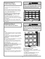
Page 29: ...nterclockwise Make 10 degree turn adjustments until the door stops easily After each adjustment run the opener through a complete travel cycle If the door doesn t open at least 5 feet Increase UP Open...

Page 30: ...ed 30 Adjustment Step 3 Test the Protector System Press the remote control push button to open the door Place the opener carton in the path of the door Press the remote control push button to close th...

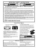
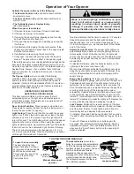
Page 31: ...eded and the safety reversal system must be checked Failure to properly adjust the opener may result in severe injury or death 5 If possible use the manual release only when the door is in a closed po...

Page 32: ...disable the motion sensor See Automatic Light Feature following The 4 1 2 minute interval can be changed to 1 1 2 2 1 2 or 3 1 2 minutes as follows Press and hold the Lock button until the light blink...

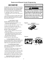
Page 33: ...r to match any additional remotes you may purchase See Accessories on page 38 To Add A Remote Control Using the Multi Function door control 1 With the door closed press and hold a remote control push...

Page 34: ...ng procedure with all remote controls The remote control has short range The garage door opens and closes by itself 1 Be sure that all remote control push buttons are off 2 Remove the bell wire from t...

Page 35: ...page 32 2 The Outside Quick Release accessory for use on garages with no service door disconnects the trolley from outside the garage in case of power failure 35 The door reverses for no apparent rea...

Page 36: ...ware illustrated on page 7 KEY PART NO NO DESCRIPTION 1 41C0472 5 Motion detecting control panel 2 41A5056 19 Multi function remote control housing screw only no circuit board 3 10A20 3V2032 Lithium B...

Page 37: ...harness assembly with plug 6 41A5021 5E Receiver logic board assembly Complete with Logic board 7 41A3673 1 End panel w all labels 8 175B88M Light socket 9 108D34 Lens KEY PART NO NO DESCRIPTION 10 3...

Page 38: ...opener light will blink three times Release the button 2 Press the temporary 4 digit password you have chosen then press Enter The opener light will blink four times 3 To set the number of hours this...

Page 39: ...8 31 Manual Release Rope and Handle Lockout feature 32 Manual disconnect 32 Safety warnings 11 19 31 32 Opener Terminals Door control connections 18 Safety reversing sensor connections 23 Outside Keyl...

Page 40: ...or reconditioned unit of the same or equal design Obtaining Service It s as easy as calling our toll free hotline at 1 888 528 6305 We will then 1 attempt to solve the problem with you over the phone...

Reviews: