background image

15

INSTALLATION STEP 10

Install The Protector System

®

The safety reversing sensor must be connected and aligned 
correctly before the door operator will move in the down 
direction. 

IMPORTANT INFORMATION ABOUT THE SAFETY 
REVERSING SENSOR

When properly connected and aligned, the sensor will detect 
an obstacle in the path of its electronic beam. The sending 
sensor transmits an invisible light beam to the receiving 
sensor. If an obstruction breaks the light beam while the door 
is closing, the door will stop and reverse to full open position, 
and the operator lights will fl ash 10 times.

The units must be installed inside the building so that the 
sending and receiving sensors face each other across the 
door, no more than 6" (15 cm) above the fl oor. Either can be 
installed on the left or right of the door as long as the sun 
never shines directly into the receiving sensor.

If it is necessary to mount the units on the wall, the brackets 
must be securely fastened to a solid surface such as the wall 
framing. If installing in masonry construction, add a piece of 
wood at each location to avoid drilling extra holes in masonry 
if repositioning is necessary. 

The invisible light beam path must be unobstructed. No part 
of the door (or door tracks, springs, hinges, rollers or other 
hardware) may interrupt the beam while the door is closing.

Facing the door from inside the building  

Be sure power is NOT connected to the door operator 
BEFORE installing the safety reversing sensor.
To prevent SERIOUS INJURY or DEATH from a closing 
door:
•  Correctly connect and align the safety reversing 

sensor. This required safety device MUST NOT be 
disabled.

•  Install the safety reversing sensor so beam is NO 

HIGHER than 6" (15 cm) above the fl oor.

Safety Reversing Sensor 
6" (15 cm) max. above fl oor 

Safety Reversing Sensor 
6" (15 cm) max. above fl oor

Invisible Light Beam 
Protection Area

Summary of Contents for ATS 2113X 1/2 HP

Page 1: ...ation The door WILL NOT CLOSE unless the Protector System is connected and properly aligned Periodic checks of the operator are required to ensure safe operation The model number label is located on the front panel of your operator DO NOT exceed 8 complete cycles of door operation per hour FOR RESIDENTIAL AND LIGHT DUTY COMMERCIAL USE INSTALL ON SECTIONAL DOORS ONLY Para Manual en Español ir a Lif...

Page 2: ... 25 Care of your door operator 26 Having a problem 27 28 Programming 29 31 Security 3 Button Remote Control Programming Optional 29 To add or change a Keyless Entry PIN Optional 30 Multi Function Door Control Optional 31 Repair Parts 32 33 Rail assembly parts 32 Installation parts 32 Operator parts 33 Accessories 34 Notes 35 Repair Parts and Service 36 Warranty 36 TABLE OF CONTENTS When you see th...

Page 3: ...US INJURY or DEATH ALWAYS call a trained door systems technician if door binds sticks or is out of balance An unbalanced door may NOT reverse when required NEVER try to loosen move or adjust door door springs cables pulleys brackets or their hardware ALL of which are under EXTREME tension Disable ALL locks and remove ALL ropes connected to door BEFORE installing and operating door operator to avoi...

Page 4: ...fety reversal system may NOT work properly The floor or the door MUST be repaired to eliminate the gap Horizontal and vertical reinforcement is needed for lightweight doors fiberglass steel aluminum door with glass panels etc See page 19 for details Header Wall Wall Mounted Door Control Safery Reversing Sensor Torsion Spring OR Vertical Centerline of Door Extension Spring Access Door Rail Door Sprin...

Page 5: ...Safety Labels and Literature The Protector System 2 Safety Reversing Sensors 1 Sending Sensor and 1 Receiving Sensor with 2 Conductor White White Black Bell Wire attached Rail Trolley Chain Pulley Bracket C Wrap 2 HARDWARE INVENTORY Assembly Hardware Installation Hardware Hardware for Safety Reversing Sensor Washered Bolt 5 16 18x1 2 2 Hex Bolt 5 16 18x7 8 4 Lag Screw 1 4 x1 1 2 4 Mounted in Opera...

Page 6: ...btain more chain slack Insert the second washered bolt Use only the bolts previously removed from operator 2 Tighten both bolts securely through the rail into the operator as shown 3 Position the rail support bracket on the operator 4 Attach the bracket to the rail with 5 16 18x7 8 hex bolts and lock washers DO NOT overtighten 5 Attach the bracket to the operator by inserting a 5 16 18x1 2 washere...

Page 7: ...AND FOLLOW ALL INSTALLATION WARNINGS AND INSTRUCTIONS 2 Install door operator ONLY on properly balanced and lubricated door An improperly balanced door may NOT reverse when required and could result in SEVERE INJURY or DEATH 3 ALL repairs to cables spring assemblies and other hardware MUST be made by a trained door systems technician BEFORE installing operator 4 Disable ALL locks and remove ALL ro...

Page 8: ...wn Draw an intersecting horizontal line on the header wall 2 5 cm above the high point This height will provide travel clearance for the top edge of the door Proceed to Installation Step 2 page 9 To prevent possible SERIOUS INJURY or DEATH Header bracket MUST be RIGIDLY fastened to structural support on header wall or ceiling otherwise door might NOT reverse when required DO NOT install header bra...

Page 9: ...ING HEADER BRACKET INSTALLATION 1 Extend the vertical centerline onto the ceiling as shown 2 Center the bracket on the vertical mark no more than 6 15 cm from the wall Make sure the arrow is pointing toward the wall The bracket can be mounted flush against the ceiling when clearance is minimal 3 Mark the side holes Drill 3 16 pilot holes and fasten bracket securely to a structural support with lag ...

Page 10: ...aise the operator onto a stepladder You will need help at this point if the ladder is not tall enough 2 Open the door all the way and place a 2x4 laid flat on the top section beneath the rail 3 If the top section or panel hits the trolley when you raise the door pull down on the trolley release arm to disconnect inner and outer sections Slide the outer trolley toward the motor unit The trolley can ...

Page 11: ...nd nuts 6 Check to make sure the rail is centered over the door or in line with the header bracket if the bracket is not centered above the door 7 Remove the 2x4 Operate the door manually If the door hits the rail raise the header bracket NOTE DO NOT connect power to operator at this time Figure 1 Figure 2 To avoid possible SERIOUS INJURY from a falling door operator fasten it SECURELY to structur...

Page 12: ... permanently attach the entrapment warning label to the wall near the door control and the manual release safety reverse test in a prominent location on the inside of the door NOTE DO NOT connect the power and operate the operator at this time The trolley will travel to the full open position but will not return to the close position until the sensor beam is connected and properly aligned See Safe...

Page 13: ...le to pull door open or closed If rope knot becomes untied you could fall To prevent possible OVERHEATING of the endpanel or light socket DO NOT use short neck or specialty light bulbs DO NOT use halogen bulbs Use ONLY incandescent INSTALLATION STEP 8 Attach the Emergency Release Rope and Handle 1 Thread one end of the rope through the hole in the top of the red handle so NOTICE reads right side u...

Page 14: ...3 Connect the black line wire to the screw on the brass terminal the white neutral wire to the screw on the silver terminal and the ground wire to the green ground screw The operator must be grounded 4 Reinstall the cover To avoid installation difficulties do not run the operator at this time To prevent possible SERIOUS INJURY or DEATH from electrocution or fire Be sure power is NOT connected to the...

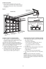
Page 15: ...ever shines directly into the receiving sensor If it is necessary to mount the units on the wall the brackets must be securely fastened to a solid surface such as the wall framing If installing in masonry construction add a piece of wood at each location to avoid drilling extra holes in masonry if repositioning is necessary The invisible light beam path must be unobstructed No part of the door or ...

Page 16: ...et assemblies to the same distance out from mounting surface Make sure all door hardware obstructions are cleared Tighten the nuts securely Door Track Installation Discard slotted bracket Drill 3 8 holes in each track and fasten securely with hardware as shown in Figure 3 HARDWARE SHOWN ACTUAL SIZE Screw 10 32x3 8 Carriage Bolt 1 4 20x1 2 Lag Screw 1 4 x1 1 2 Lock Nut 1 4 20 Lock Nut 10 32 Staples...

Page 17: ...e instructions below 1 Cut the end of the safety reversing sensor wire making sure there is enough wire to reach the pre installed wires from the wall Figure 8 2 Separate the safety reversing sensor wires and strip 1 4 6 mm of insulation from each end Choose two of the pre installed wires and strip 1 4 6 mm of insulation from each end Make sure that you choose the same color pre installed wires fo...

Page 18: ...eam path is not obstructed alignment is required 2 Loosen the sending sensor wing nut and readjust aiming directly at the receiving sensor Lock in place 3 Loosen the receiving sensor wing nut and adjust sensor until it receives the sender s beam When the green indicator light glows steadily tighten the wing nut TROUBLESHOOTING THE SAFETY REVERSING SENSORS 1 If the sending sensor indicator light do...

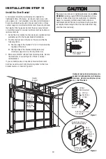
Page 19: ...previously marked vertical guideline used for the header bracket installation 2 Position the bracket on the face of the door within the following limits A The top edge of the bracket 2 4 5 10 cm below the top edge of the door B The top edge of the bracket directly below any structural support across the top of the door 3 Mark and drill 5 16 left and right fastening holes Secure the bracket as show...

Page 20: ...oles in curved arm are above holes in straight arm disconnect straight arm Cut about 6 15 cm from the solid end Reconnect to trolley with cut end down as shown Bring arm sections together Find two pairs of holes that line up and join with 5 16 18x7 8 hex bolts lock washers and nuts 5 Proceed to Adjustment Step 1 page 21 Trolley will re engage automatically when operator is operated Figure 1 Figure...

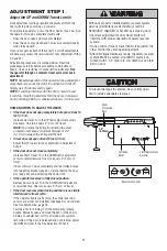
Page 21: ...P open force as explained in Adjustment Step 2 If the door does not close completely Increase down travel Turn the DOWN limit adjustment screw counterclockwise One turn equals 2 5 cm of travel If door still won t close completely and the trolley bumps into the pulley bracket page 4 try lengthening the door arm page 20 and decreasing the down limit If the operator reverses in fully closed position ...

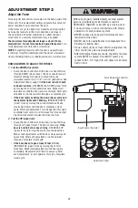
Page 22: ...INCREASE DOWN close force by turning the control clockwise Make small adjustments until the door completes a close cycle After each adjustment run the operator through a complete travel cycle Do not increase the force beyond the minimum amount required to close the door 2 Test the UP open force Grasp the door bottom when the door is about halfway through UP open travel The door should stop If the ...

Page 23: ...r System 1 Press the remote control push button to open the door 2 Place the operator carton in the path of the door 3 Press the remote control push button to close the door The door will not move more than an inch 2 5 cm and the operator lights will flash The door operator will not close from a remote if the indicator light in either sensor is off alerting you to the fact that the sensor is misali...

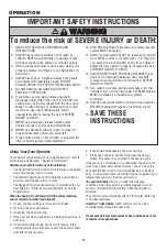
Page 24: ... operation per hour in commercial applications OPERATION IMPORTANT SAFETY INSTRUCTIONS To reduce the risk of SEVERE INJURY or DEATH WARNING WARNING 1 READ AND FOLLOW ALL WARNINGS AND INSTRUCTIONS 2 ALWAYS keep remote controls out of reach of children NEVER permit children to operate or play with door control push buttons or remote controls 3 ONLY activate door when it can be seen clearly it is pro...

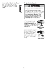
Page 25: ...R use handle to pull door open or closed If rope knot becomes untied you could fall LOCKOUT POSITION Trolley Release Arm Emergency Release Handle Down and Back MANUAL DISCONNECT POSITION Trolley Release Arm Emergency Release Handle Pull Down The door should be fully closed if possible Pull down on the emergency release handle and lift the door manually To reconnect the door to the operator press t...

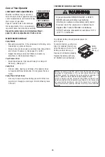
Page 26: ...operator rail Reapply a small layer of white lithium grease to the rail FORCE CONTROLS LIMIT CONTROLS NOTICE To comply with FCC and or Industry Canada IC rules adjustment or modifications of this receiver and or transmitter are prohibited except for changing the code setting or replacing the battery THERE ARE NO OTHER USER SERVICEABLE PARTS Tested to Comply with FCC Standards FOR HOME OR OFFICE US...

Page 27: ...acked insulation or metal siding 5 Operator noise is disturbing in living quarters of home If operational noise is a problem because of proximity of the operator to the living quarters the Vibration Isolator Kit 89LM can be installed This kit was designed to minimize vibration to the house and is easy to install 6 The door opens and closes by itself Be sure that all remote control push buttons are...

Page 28: ...springs may be broken Close the door and use the emergency release handle to disconnect the trolley Open and close the door manually A properly balanced door will stay in any point of travel while being supported entirely by its springs If it does not disconnect the operator and call a trained door systems technician Do not increase the force to operate the operator 15 The operator motor hums brie...

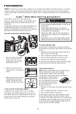
Page 29: ... the operator lights flash release all buttons Test by pressing the remote push button The operator lights should turn on or off but the door should not move To Erase All Codes From Motor Unit Memory To deactivate any unwanted remote first erase all codes Press and the hold LEARN button on motor unit until the learn indicator light goes out approximately 6 seconds All previous codes are now erased R...

Page 30: ...e To set a temporary PIN You may authorize access by visitors or service people with a temporary 4 digit PIN After a programmed number of hours or number of accesses this temporary PIN expires and will no longer open the door It can be used to close the door even after it has expired To set a temporary PIN 1 Press the four buttons for your personal entry PIN not the last temporary PIN then press a...

Page 31: ...n page 15 To prevent possible SERIOUS INJURY or DEATH from electrocution Be sure power is NOT connected BEFORE installing door control Connect ONLY to 24 VOLT low voltage wires To prevent possible SERIOUS INJURY or DEATH from a closing door Install door control within sight of door out of reach of children at a minimum height of 5 feet 1 5 m and away from ALL moving parts of door NEVER permit chil...

Page 32: ...Emergency release rope handle assembly 4 12B374 Door bracket 5 12B380 Door bracket plate 6 41A4353 Header bracket with clevis pin fastener 7 41A4373ATS Photoelectric Sensor Kit receiving and sending sensors with 3 9 m 2 conductor bell wire attached and mounting brackets 8 178B35 Curved door arm section 9 12B483 C Wrap bracket 10 178B34 Straight door arm section 178B73 Straight door arm section 14 ...

Page 33: ...with grease Roll pins 2 5 143D100 1 Front end panel 6 175B88 Light socket 7 30B532 Capacitor 8 12A461 Capacitor bracket 9 41A3150 Terminal block with screws KEY PART NO NO DESCRIPTION 10 41D4509 Replacement motor bracket assembly Complete with Motor worm bracket bearing assembly 11 41A4593 5 Cover 12 81C253 Helical gear retainer with grease 13 41A5640 Limit switch assembly 14 41C4398A RPM sensor a...

Page 34: ...ssword can be limited to a programmable number of hours or entries Multi Function Door Control Panel Provides a Lock Feature which prevents operation of door operator from portable remotes and a Light Feature for constant light 78LM 12 Foot 3 66 m Complete Rail To allow a 12 foot 3 66 m door to open fully CD1012 14 Foot 4 27 m Complete Rail To allow a 14 foot 4 27 m door to open fully NOTE Require...

Page 35: ...35 NOTES ...

Page 36: ...d warranty will be repaired or replaced at Seller s sole option at no cost to you and returned pre paid Defective parts will be repaired or replaced with new or factory rebuilt parts at Seller s sole option ALL IMPLIED WARRANTIES FOR THE PRODUCT INCLUDING BUT NOT LIMITED TO ANY IMPLIED WARRANTIES OF MERCHANTABILITY AND FITNESS FOR A PARTICULAR PURPOSE ARE LIMITED IN DURATION TO THE ONE YEAR LIMITE...

Page 37: ...orte pour s y reporter ultérieurement La porte NE SE FERMERA PAS si le Système Protector n est pas branché et réglé correctement Pour un bon fonctionnement en toute sécurité de cet actionneur le vérifier et le régler périodiquement Vous trouverez le numéro de modèle sur un décalque situé sur le couvercle de l actionneur NE PAS faire fonctionner la porte plus de 8 fois par heure POUR USAGE RÉSIDENT...

Page 38: ...n de la télécommande à trois boutons Security Facultatif 29 Pour ajouter ou modifier un NIP d entrée sans clé Facultatif 30 Panneau de commande de porte multifonction Facultatif 31 Pièces de réparation 32 33 Pièces d assemblage du rail 32 Pièces pour la pose 32 Pièces d actionneur 33 Accessoires 34 Remarques 35 Pièces de réparation et service 36 Garantie 36 TABLE DES MATIÈRES Lorsque vous verrez c...

Page 39: ... métaux Marteau Clé à molette Tournevis Pince universelle Perceuse Escabeau Clé à douille et douilles de 1 2 po et 7 16 de po Forets de 3 16 de po 5 16 de po et 5 32 de po Spécifications Tension 120 Vca 60 Hz SEULEMENT Courant 5 6 A Niveau de chargement 300 po livre s 8 cycles à l heure Hauteur maximum de la porte 4 27m 14 pi Zone maximum de la porte 4 27m x 3 66m 14 pi x 12 pi Ne pas dépasser 168 ...

Page 40: ...ncher ou la porte pour éliminer l espace Il faudra poser des renforts horizontaux et verticaux dans le cas d une porte légère en fibre de verre en acier en aluminium en panneaux de verre etc Se reporter à la page 19 pour plus de détails Linteau Commande de porte murale Détecteur inverseur de sécurité Ressort de torsion OU Ligne du centre vertical de la porte Ressort de traction Porte d accès Rail R...

Page 41: ...é 2 INVENTAIRE DES FIXATIONS Fixations pour le montage Fixations pour la pose Fixations pour détecteur inverseur de sécurité Boulon à rondelle frein de Boulon hexagonale de Tire fond de 1 4 de po x 1 1 2 de po 4 5 16 de po 18 x 1 2 de po 2 5 16 de po 18 x 7 8 de po 4 Boulon à tête bombée et à collet carré de montées dans l actionneur Écrou de 5 16 de po 18 4 1 4 de po 20 x 1 2 de po 4 Boulon à têt...

Page 42: ... deux boulons fortement à travers le rail et dans l actionneur comme illustré 3 Positionner le support du rail sur l actionneur 4 Attachez le support au rail avec les boulon hexagonale de 5 16 de po 18 x 7 8 de po et leurs rondelles freins NE PAS trop serrer 5 Attachez le support à l actionneur en insérant une boulon rondelle de 5 16 de po 18 x 1 2 de po à travers un orifice dans chaque bride latér...

Page 43: ...librée peut NE PAS remonter au besoin et pourrait provoquer des BLESSURES GRAVES ou LA MORT 3 TOUTES les réparations aux câbles ensembles de ressort et autres ferrures de montage DOIVENT être confiées à un technicien formé en systèmes de porte AVANT de poser l actionneur 4 Désactiver TOUTES les serrures et retirer TOUTES les cordes raccordées à la porte AVANT de poser l actionneur afin d éviter un e...

Page 44: ...us du point le plus haut Cette hauteur permettra d obtenir un dégagement suffisant pour le passage de la partie supérieure de la porte Passer à la 2e Pose opération page 9 Pour prévenir d éventuelles BLESSURES GRAVES ou la MORT Le support de linteau DOIT être fixé DE MANIÈRE RIGIDE à la solive sur le linteau ou le plafond sinon la porte pourrait NE PAS remonter au besoin NE PAS poser le support de l...

Page 45: ...DE LINTEAU AU PLAFOND 1 Prolonger l axe vertical sur le plafond comme illustré 2 Centrer le support sur l axe vertical à 15 cm 6 pouces au maximum du mur S assurer que la flèche est orientée vers le mur Le support peut être encastré dans le plafond si le dégagement n est pas suffisant 3 Marquer les trous latéraux Percer des avant trous de 5 mm 3 16 de po et fixer fermement le support sur une solive d...

Page 46: ...er sur un escabeau Si l escabeau n est pas assez haut demander de l aide 2 Ouvrir complètement la porte et mettre un 2 x 4 à plat sur sa partie supérieure sous le rail 3 Si le panneau ou la section du dessus vient en contact avec le chariot lorsqu on lève la porte tirer sur la biellette de dégagement du chariot pour dégager le chariot intérieur du chariot extérieur Faire glisser le chariot extérie...

Page 47: ...inteau si le support n est pas centré au dessus de la porte 7 Retirer le 2 x 4 Faire fonctionner la porte manuellement Si la porte frappe le rail lever le support de linteau REMARQUE NE PAS mettre l actionneur sous tension à ce stade Figure 1 Figure 2 Pour éviter d éventuelles BLESSURES GRAVES par suite de la chute d un actionneur fixer actionneur SOLIDEMENT aux solives On DOIT utiliser des ancrage...

Page 48: ...version de sécurité ouverture manuelle bien en vue à l intérieur de la porte REMARQUE NE PAS brancher et faire fonctionner l actionneur pour le moment Le chariot se déplacera jusqu à la position complètement ouverte mais ne reviendra pas à la position fermée avant que le faisceau détecteur soit branché et correctement aligné Voir les instructions au sujet du détecteur inverseur de sécurité à parti...

Page 49: ...ermer la porte Il y a risque de chute si le nœud de la corde se défait Pour éviter toute SURCHAUFFE éventuelle du panneau d éclairage NE PAS utiliser d ampoules à col court ou de forme spéciale NE PAS utiliser d ampoules halogène Utiliser UNIQUEMENT des ampoules incandescentes POSE 8e OPÉRATION Pose de la corde et de la poignée de déclenchement d urgence 1 Faire passer une extrémité de la corde da...

Page 50: ...r sur la vis de la borne en laiton le fil blanc neutre sur la vis de la borne en argent puis le fil de terre sur la vis verte de terre L actionneur doit obligatoirement être mis à la terre 4 Reposer le couvercle Pour éviter les difficultés pendant la pose ne pas faire fonctionner l actionneur pour le moment Pour prévenir d éventuelles BLESSURES GRAVES ou la MORT par suite d électrocution ou d un ince...

Page 51: ...ent être fixés fermement à une surface solide telle que la charpente du mur Si la pose se fait dans une construction en maçonnerie ajouter un morceau de bois à chaque endroit pour éviter de percer des trous supplémentaires dans la maçonnerie si un repositionnement est nécessaire Il ne doit y avoir aucun obstacle sur le parcours du faisceau de lumière invisible Aucune partie de la porte ni les guide...

Page 52: ...che et droit à la même distanc de la surface de fixation S assure qu aucune piéce de fixation de la porte ne gêne le faisceau lumineux Serrer fermement les écrous Installation sur coulisse de porte Eliminer les supports de fixation avec fente Percer des trous de 3 8 de pouce dans chaque coulisse et attacher solidement avec les fixations illustrée à la Figure 3 GRANDEUR RÉELLE DES FIXATIONS Vis N 10 32...

Page 53: ...ctions ci dessous 1 Coupez l extrémité du câble du capteur de l inverseur de sécurité en vous assurant qu il reste suffisamment de longueur pour atteindre les câbles préinstallés depuis le mur Figure 8 2 Séparez les câbles du capteur de l inverseur de sécurité et dénudez sur chaque extrémité 6 mm 1 4 de po de l isolant Choisissez deux des câbles préinstallés et dénudez sur chaque extrémité 6 mm 1 4...

Page 54: ... 2 Desserrer l écrou de la détecteur émettrice et ajuster de façon à ce qu elle vise directement la détecteur réceptrice Serrer l écrou 3 Desserrer l écrou de la détecteur réceptrice et régler le détecteur jusqu à ce qu il reçoive le faisceau de la détecteur émettrice Lorsque le témoin vert reste allumé serrer l écrou DÉPANNAGE DES DÉTECTEURS INVERSEURS DE SÉCURITÉ 1 Si lorsque la pose est terminé...

Page 55: ... la porte en respectant les limites suivantes A Le bord supérieur du support doit être entre 5 et 10 cm 2 et 4 pouces plus bas que le bord supérieur de la porte B Le bord supérieur du support doit être placé directement sous le support structurel placé en haut de la porte 3 Repérer et percer les trous de fixation gauche et droit de 5 16 de pouce Faire tenir le support comme il est illustré à la Fig...

Page 56: ...mettent aux biellettes d être plus solides 4 Figure 3 Méthode alternative Si les trous de la biellette courbée sont trop hauts démonter la biellette droite et couper 15 cm 6 po du bout Refixer la biellette droite sur le chariot en orientant la partie coupée vers le bas comme illustré Rapprocher les biellettes Aligner deux paires de trous et raccorder les deux biellettes avec les boulons hexagonale ...

Page 57: ...ées elle remontera COMMENT ET QUAND RÉGLER LES COURSES Si la porte ne s ouvre pas complètement mais s ouvre d au moins cinq pieds Augmenter la course d ouverture en tournant la vis de réglage UP à droite Un tour complet de la vis correspond à 5 cm 2 po de course REMARQUE Pour empêcher le chariot de frapper le boulon de protection du couvercle garder une distance minimale de 5 à 10 cm 2 po à 4 po e...

Page 58: ...à ce que la porte fasse un cycle de fermeture complet Après chaque réglage Faire un cycle complet à l actionneur Ne pas augmenter la force au delà du niveau nécessaire pour fermer la porte 2 Vérification de la force d ouverture UP Pendant que la porte est environ à mi chemin de sa course d ouverture essayer de l arrêter à la main La porte doit s arrêter S il est difficile de retenir la porte ou si l...

Page 59: ...ur ouvrir la porte 2 Mettre la boîte en carton de l actionneur dans la course de la porte 3 Appuyer sur le bouton poussoir de la télécommande pour fermer la porte La porte ne se déplacera pas de plus de 2 5 cm un pouce et les lumières de actionneur clignoteront La porte ne se fermera pas à l aide d une télécommande si le témoin lumineux d un des deux détecteurs est éteint ce qui avertit que le dét...

Page 60: ...en usage commercial FONCTIONNEMENT IMPORTANTES CONSIGNES DE SÉCURITÉ 1 LIRE ET SUIVRE TOUS LES AVERTISSEMENTS ET INSTRUCTIONS 2 TOUJOURS garder les télécommandes hors de la portée des enfants Ne JAMAIS laisser les enfants faire fonctionner les télécommandes ou les boutons poussoirs de la commande de porte ou jouer avec ceux ci 3 Actionner la porte UNIQUEMENT lorsqu on peut la voir clairement qu el...

Page 61: ... y a risque de chute si le nœud de la corde se défait Dans la mesure du possible la porte doit être complètement fermée Tirer la poignée de déclenchement d urgence et lever la porte manuellement Pour rattacher la porte à l actionneur appuyer sur la barre poussoir de la commande de porte La fonction de verrouillage empêche le chariot de se réenclencher automatiquement Tirer la poignée de déclenchem...

Page 62: ... Appliquez de nouveau une fine couche de graisse blanche au lithium sur le rail COMMANDES DE FORCE COMMANDES DE COURSE AVIS Les règles de la FCC ou d Industrie Canada IC ou les deux interdisent tout ajustement ou toute modification de ce récepteur et ou de cet émetteur sauf pour modifier le code ou pour remplacer la pile IL N EXISTE AUCUNE AUTRE PIÈCE SUSCEPTIBLE D ÊTRE ENTRETENUE PAR L UTILISATEUR...

Page 63: ...à cause d une porte métallique d isolation à revers d aluminium ou avec revêtement métallique 5 L actionneur se fait fortement entendre dans la résidence quand il fonctionne Un nécessaire d insonorisation 89LM peut être posé Cet équipement est conçu pour minimiser les vibrations à la maison et est facile à installer 6 La porte s ouvre et se ferme toute seule S assurer que tous les boutons poussoir...

Page 64: ...ien les ressorts sont cassés Fermer la porte et utiliser la poignée de déclenchement d urgence pour détacher le chariot Ouvrir et fermer la porte à la main Une porte bien équilibrée restera à sa position d arrêt entièrement supportée par les ressorts le cas contraire détacher l actionneur et appeler un technicien formé en systèmes de porte Ne pas augmenter la force pour faire fonctionner la porte ...

Page 65: ...e de l actionneur doit s allumer ou s éteindre sans que la porte ne bouge Pour effacer tous les codes de la mémoire du moteur Pour inactiver toute télécommande non désirée effacer d abord tous les codes Enfoncer et tenir le bouton d apprentissage du moteur jusqu à ce que le témoin lumineux learn s éteigne environ 6 secondes Tous les codes précédents sont maintenant effacés Reprogrammer chaque télé...

Page 66: ...n NIP temporaire Vous pouvez autoriser l accès aux visiteurs ou aux techniciens de service à l aide d un NIP temporaire à 4 chiffres Après un nombre programmé d heures ou un nombre programmé d utilisations ce NIP temporaire vient à expiration et n ouvre plus la porte On peut l utiliser pour fermer la porte une fois qu il a expiré Pour définir un NIP temporaire 1 Appuyer sur les quatre boutons corre...

Page 67: ... d électrocution S assurer que le courant est coupé AVANT de poser la commande de porte Raccorder UNIQUEMENT à des fils basse tension 24 V Pour prévenir d éventuelles BLESSURES GRAVES ou la MORT par suite d une porte qui se ferme Poser la commande de porte en vue de la porte hors de la portée des enfants à une hauteur minimum de 1 5 m 5 pieds et à l écart de TOUTES les pièces mobiles de la porte Ne...

Page 68: ... à 2 conducteurs 3 41A2828 Poignée et corde pour fonctionnement d urgence 4 12B374 Support de porte 5 12B380 Plaque de support de porte 6 41A4353 Support de linteau avec axe de chape et fixation 7 41A4373ATS Nécessaire de capteur de sécurité capteurs de réception et de transmission avec fi l de sonnerie à deux conducteurs de 3 pi 0 9 m 8 178B35 Biellette courbée 9 12B483 Profilé 10 178B34 Biellette d...

Page 69: ...rique 2 5 143D100 1 Panneau d extrémité avec toutes les étiquettes 6 175B88 Douille d ampoule 7 30B532 Condensateur 8 12A461 Support de condensateur 9 41A3150 Bornier avec vis N DE RÉF PIÈCE DÉSIGNATION 10 41D4509 Ensemble de rechange moteur et support de montage Comprend Moteur vis sans fin support roulement 11 41A4593 5 Couvercle 12 81C253 Pignon hélicoïdal avec flasque et graisse 13 41A5640 Inter...

Page 70: ... un nombre programmable d heures ou d entrées Commande de porte multi fonction Comporte une fonction de verrouillage qui empêche le fonctionnement de la porte à l aide d une télécommande et une fonction d éclairage pour un éclairage constant 78LM Rail complet de 3 66 m 12 pieds Pour permettre à une porte de 3 66 m 12 pieds de s ouvrir complètement CD1012 Rail complet de 4 27 m 14 pieds Pour permet...

Page 71: ...35 REMARQUES ...

Page 72: ...n du Vendeur sans frais pour l acheteur puis retournés en port payé Les pièces défectueuses seront réparées ou remplacées par de nouvelles pièces ou des pièces remises à neuf en usine à la seule discrétion du Vendeur TOUTES GARANTIES TACITES RELATIVES À CE PRODUIT DONT SANS TOUTEFOIS S Y LIMITER TOUTE GARANTIE TACITE DE QUALITÉ MARCHANDE ET D ADAPTATION À UN USAGE PARTICULIER SONT LIMITÉES EN DURÉ...

Reviews: