background image

HELPLINE NO 08448012949

16

OrIgINaL INstructIONs

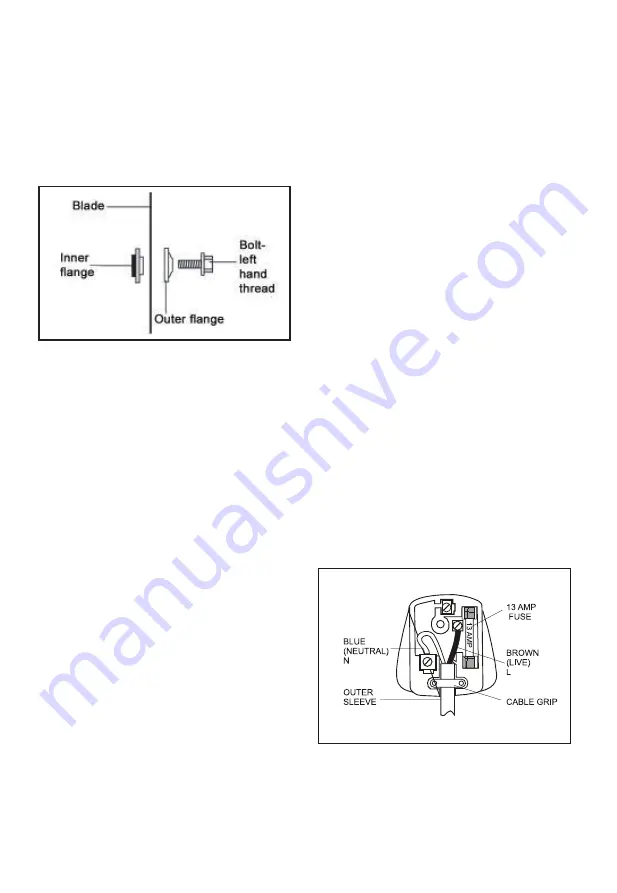
procedure in reverse order. If you want to 

take the inner flange out for cleaning, refit it 

as shown in Fig.P4

cautION: aLways

 install the blade with 

the blade teeth and the arrow printed on the 

side of the blade pointing down at the front 

of the saw. The direction of blade rotation 

is also stamped with an arrow on the upper 

blade guard.

Fig. P4

3. rEPLacINg tHE carbON brusHEs

Check the carbon brushes regularly. If the 

carbon brushes are worn down to about 

4mm, replace them with the new set (not 

supplied). It must be replaced in pairs.

With a suitable slotted screwdriver turn the 

cap anti-clockwise until the carbon brush is 

released, replace the brush and make sure 

that they locate well and are secured within 

the brush retainer.

4. MOVINg tHE saw (see E1)

1) When transporting the saw with fixed 

locations, make sure that the saw head is 

locked in the lower position.

2) The rotary table locking knob, the bevel 

lock lever and the slide rod securing knob, 

must all be securely tightened.

3) Use the transportation handle to lift 

the saw. Do not lift the saw by the switch 

handle.

PLug rEPLacEMENt

Your Power Tool is supplied with a fitted 

plug, however if you need to fit a new plug 

follow

the instruction below.

IMPOrtaNt

The wires in the mains lead are coloured in 

accordance with the following code:

blue = Neutral   brown = Live

As the colours of the wires in the mains 

lead of this appliance may not correspond 

with the coloured markings identifying the 

terminals in your plug, proceed as follows:

The wire which is coloured blue must be 

connected to the terminal which is marked 

with 

N

.

The wire which is coloured brown must be 

connected to the terminal which is marked 

with the letter L .

If a 13 AMP (BS 1363/A) Plug is used, a 

13 AMP Fuse must be fitted, or if any other 

type of plug is used a 13 AMP Fuse must 

be fitted, either in the Plug or Adaptor, or 

on the Distribution Board.

NOtE:

 If a moulded plug is fitted and has 

to be removed take great care in disposing 

of the plug and severed cable, it must 

be destroyed to prevent engaging into a 

socket.

If the supply cord is damaged it must be 

replaced by a service agent or a similarly 

qualified person in order to avoid hazard.

Summary of Contents for BMS210MS.1

Page 1: ...1700W 210mm Sliding Mitre Saw with Laser BMS210MS 1 ORIGINAL INSTRUCTIONS...

Page 2: ...not intended for example do not use circular saws to cut tree limbs or logs 8 Dress properly Do not wear loose clothing or jewellery they can be caught in moving parts Non skid footwear is recommended...

Page 3: ...rules Repairs should only be carried out by qualified persons using original spare parts otherwise this may result in considerable danger to the user Additional safety instructions for your band saw...

Page 4: ...laser beam shall not be deliberately aimed at another person and shall be prevented from being directed towards the eye of a person for longer than 0 25 seconds 4 Always ensure the laser beam is aime...

Page 5: ...maged This product has been marked with a symbol relating to removing electric and electronic waste This means that this product shall not be discarded with household waste but that it shall be return...

Page 6: ...9 Rotary Table 10 Fence 11 Saw Blade 12 Lower Blade Guard 13 Safety Guard Mounting Plate 14 Carbon Brush Cap 15 Safety Release Lever 16 Trigger Switch 17 Handle 18 Upper Blade Guard 19 Transportation...

Page 7: ...on 4 51m s2 Uncertainty K 1 5m s WARNING The vibration emission value during actual use of the power tool can differ from the declared value depending on the ways in which the tool is used dependant o...

Page 8: ...spread any high vibration tool use across a number of days ACCESSORIES dust bag 1 Support stand 1 work clamp 1 extension rail 2 blade spanner 1 Blade 210x 30x2 6mm 24T 1 Battery cell 2 We recommend th...

Page 9: ...ys cuts in wood Horizontal mitre angles of 45 to 45 as well as vertical bevel angles of 0 to 45 are possible ASSEMBLY WARNING To prevent the accidental starting that could cause possible serious perso...

Page 10: ...e saw and is fully adjustable to suit the size of the workpiece 2 Do not operate the saw without clamping the workpiece 3 Make sure that the work clamp securing screws are tightened a2 Fig C 5 MOUNTIN...

Page 11: ...g your forefinger simply press the safety release lever It will then be feasible to push the saw head down by the handle 6 Continue to move the saw head down smoothly and make the cut exerting only ge...

Page 12: ...re it is fully tightened before cutting 6 BEVEL CUT See I1 I2 A bevel cut is made at 0 miter and any bevel angle in the range of 0 to 45 left It can be made as either a chop cut or a cross pull cut de...

Page 13: ...securely tighten the lock nut There is also a secondary depth stop it can also be used for partial through cutting To do the trench cutting proceed as follows 1 Pull out the depth stop lever f 2 Loos...

Page 14: ...through the ventilation slots This is normal and will not damage your power tool If the supply cord of this power tool is damaged it must be replaced by a specially prepared cord available through th...

Page 15: ...nnect the saw from the power supply Lower the saw head until the blade securing bolt can be seen Press the blade spindle lock k and rotate the blade until it is locked then loosen and remove the blade...

Page 16: ...l be securely tightened 3 Use the transportation handle to lift the saw Do not lift the saw by the switch handle PLUG REPLACEMENT Your Power Tool is supplied with a fitted plug however if you need to...

Page 17: ...eed against manufacturing defects for a period of 12 months This does not cover the product where the fault is due to misuse abuse use in contravention of the instructions or where the product has bee...

Page 18: ......

Page 19: ......

Page 20: ......

Reviews: