


Chapter 2
2.5 Connector and Jumper Settings
Connectors are used to link the system board with other parts of the system,
including the power supply, the keyboard, and the various controllers on the
front panel of the system case.
The power supply connector is the last connection to be made while installing a
motherboard. Before connecting the power supply, please make sure it is not
connected to the power source.
Note
:
All cables are
security-proof
.
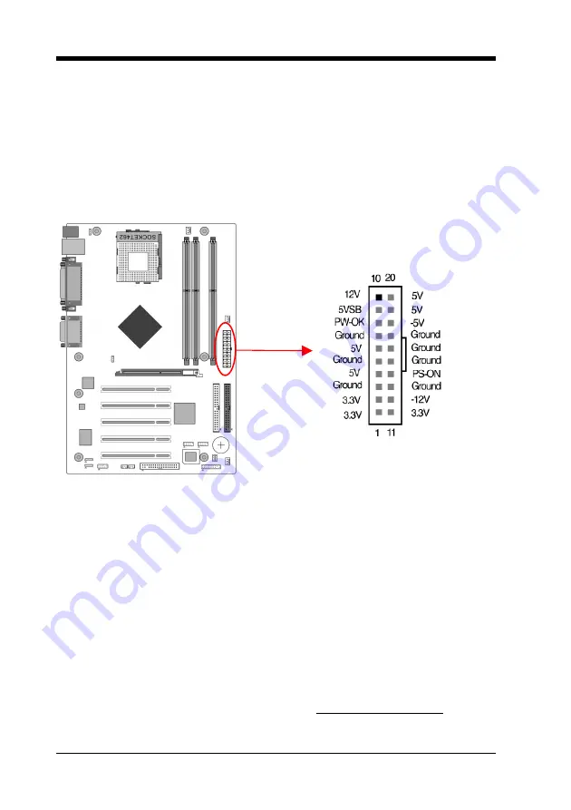
PW1 (ATX Power Supply Connector)
The power cord leading from the system's power supply to the external power
source must be the very last part connected when assembling a system. The
ATX power supply provides a single 20-pin connector interface, which
incorporates st/-5V, +/-12V, optional 3.3V and soft-power signals.
The soft-power signal, a 5V trickle supply is continuously supplied when AC
power is available. When the system is in the Soft-Off mode, this trickle supply
maintains the system in its minimum power state.
Power-On By Modem
While in Soft-Off state, if an external modem ring-up signal occurs, the system
wakes up and can be remotely accessed. You may enable this function in BIOS's
Power Management Setup menu. (See section
3.5
)
Blinking LED in Suspend Mode
While in Suspend mode, the LED light on the front panel of your computer will
flash. Suspend mode is entered by pressing the Override Power Button, pushing
the Green button on your ATX case, or enabling the Power Management and
Suspend Mode options in BIOS's Power Management menu. (See section
3.5
)
10
Summary of Contents for 7NJL3
Page 7: ...Chapter 1 1 3 7NJL3 Motherboard Layout 3...
Page 41: ...Chapter 4 3 Please select OK to continue 4 Please select Finish to restart your computer 37...
Page 43: ...Chapter 4 3 Please select Next to continue 4 Please select Next to continue 39...
Page 44: ...Chapter 4 5 Please select Next to continue 6 Please select Continue Anyway to continue 40...
Page 47: ...Chapter 5 Chapter 5 C Media 3D Audio Configuration 5 1 Speaker Out 1 Earphone 43...
Page 48: ...Chapter 5 2 Two Channel 44...
Page 49: ...Chapter 5 3 Four Channel 45...
Page 50: ...Chapter 5 4 Six Channel 46...
Page 51: ...Chapter 5 5 2 S PDIF 1 S PDIF Out Source Format 5 3 Volume Control 47...


