Modular
F1/com CV in
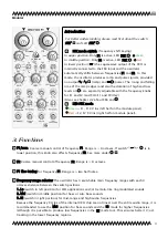
Frequency control voltage input for F1/com. Level can be adjusted by knob and
the polarity inverted with switch . See also ,
2
3
4
5 6
7
8 9
21
10
11
13 14 15 16 17
18 19
20
22
12
Objekt in Pfade:
4
4
14
Falsche Zahlen
.
F1/com CV 1V/Oct in
1V/Octave input for F1/com. See also ,
2
3
4
5 6
7
8 9
21
10
11
13 14
15 16
17
18 19
20
22
12
Objekt in Pfade:
4
4
14
Falsche Zahlen
. (1V/oct. adjustment, if
necessary, see chapter
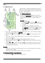
4.Adjustment
)
F2 CV in
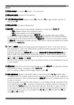
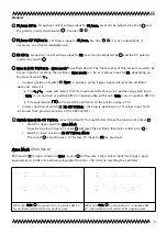
Frequency control voltage input for F2. Level can be adjusted by and the CV polarity
inverted by switch
Sync in ↕ F2 1V/Oct in (‘
Sync mode‘
new from Rev.6
) The functionality of this socket can either be
a logic input for resetting the oscillator (Sync mode)
or be a1V/octave input for F2, depending on
the state of switch
2
3
4
5 6
7
8 9
21
10
11
13 14
15 16
17
18 19
20
22
12
Objekt in Pfade:
4
4
14
Falsche Zahlen
4
8
9
10
11
12
26
24
.
•
In upper position of switch
2
3
4
5 6
7
8 9
21
10
11
13 14
15 16
17
18 19
20
22
12
Objekt in Pfade:
4
4
14
Falsche Zahlen
4
8
9
10
11
12
26
24
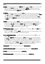
‘Sync’, a positive-going trigger signal will reset the oscillator-
wave and restart it.
▸
The / - wave will restart from its maximum deflection point (positive edge with knob
‘Gain’ in cw position or positive AM CV; negative edge with knob ‘Gain’ ccw or negative AM CV)
▸
The squarewave (
)
will restart the oscillation on the positive edge (+5V).
•
In lower position of switch
2
3
4
5 6
7
8 9
21
10
11
13 14
15 16
17
18 19
20
22
12
Objekt in Pfade:
4
4
14
Falsche Zahlen
4
8
9
10
11
12
26
24
‘F2-CV 1V/Oct.’, the plug is working as a 1V/octave input for F2
(as known from previous versions of the XR22VCOFT)
Switch Sync ↕ F2-CV 1V/Oct.
(new from Rev.6)
This switch determines the function of socket :
•
Switch in upper position:
Sync Mode
A positive-going trigger on socket will reset the oscillator (Read also under point ).
•
Switch in lower position:
F2 CV 1V/Oct. Mode
The socket is working as a 1V/Octave CV input for F2 (as previous).
Sync Mode (from Rev.6)
With switch
2
3
4
5 6
7
8 9
21
10
11
13 14
15 16
17
18 19
20
22
12
Objekt in Pfade:
4
4
14
Falsche Zahlen
4
8
9
10
11
12
26
24
in upper direction ‘Sync’; socket will become a logic signal input (for trigger/ gate/
squarewave or similar). A positive going edge from 0V→+5V (min.) is resetting the oscillator:
With knob ‘Gain’ in
cw position or a positive AM CV ,
the oscillation will restart at its
positive peak.
With knob ‘Gain’ in
ccw position or a negative AM
CV , the oscillation will restart at its
negative peak.
6
2
3
4
5 6
7
8 9
21
10
11
13 14
15 16
17
18 19
20
22
12
Objekt in Pfade:
4
4
14
Falsche Zahlen
4
2
3
4
5 6
7
8 9
21
10
11
13 14 15 16 17
18 19
20
22
12
Objekt in Pfade:
4
4
14
Falsche Zahlen
4
8
9
10
11
12
26
24


