Cetetherm AquaEfficiency
Installation, service and operating instruction
7
Flowcharts
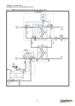
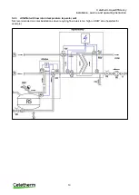
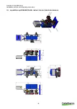
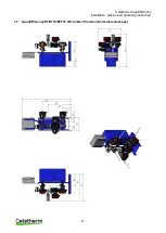
The tap water modules should be installed according to the following schematics.
Whatever type, unit model and production type (Instantaneous or Semi Instantaneous), each
pump (or pump motor when double ones) delivers 10% to 100% of the nominal primary pump
signal and 25% to 100% of the nominal secondary pump signal, to stick to the actual demand.
Cetetherm do not recommend the use of a mixing bottle on primary side of an AquaEfficiency installation,
because the mixing effect destroys the low return temperature. But the need for the differential pressure
breaker functionality of this mixing bottle is still mandatory.
On AquaEfficiency Cetetherm recommends replacing the traditional mixing bottle by a small buffer tank, named
STBI, that serves as an inertial storage tank and avoids any boiler pumping.
In case a primary vessel, named STP, is required or designed on the installation, the STBI tank becomes
unnecessary.
4.1
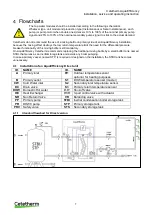
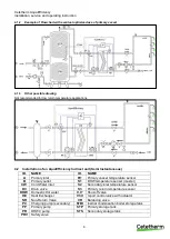
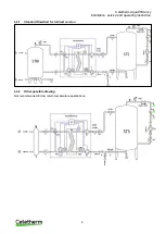
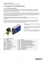
Installation of an AquaEfficiency Direct unit
ID.
NAME
ID.
NAME
A
Primary inlet
Pt1
Outdoor temperature sensor
optional, for heating purposes
B
Primary outlet
S1
DHW temperature sensor (master)
CW
Cold Water inlet
S2
Secondary inlet temperature sensor
DC
Drain valve
S3
Primary return temperature sensor
DHW
Domestic Hot water
V, V’
Shut-off valve
HE
Heat Exchanger
V3V
3-port control valve with actuator
NR
Non Return Valve
VR
Balancing valve
PP
Primary pump
STBI
Inertial condensation boiler storage tank
PR
DHWC pump
STP
Primary storage tank
PRV
Safety valve
STS
Secondary storage tank
4.1.1
Standard flowchart for Direct version


