background image

Fitting the Access Point 

22 

Access Point 


ATTENTION 

Static charges may damage or interfere with 
the electronic components of the Access 
Point. 


Do not disassemble the Access Point in rooms 
with built up static charge.   


Ensure potential equalization when working on 
the Access Point to remove any static charge. 


CAUTION 

Danger of injury by improper fitting. 


Ensure that the Access Point is only fitted by 

appropriately trained skilled personnel. 

Summary of Contents for Omega active 245510F

Page 1: ...OMEGA ACTIVE Access Point 247510F Fitting and Operating Instructions Translated fitting and operating instructions version 1 26 11 2014...

Page 2: ...ng and Operating Instructions These Fitting and Operating Instructions should be kept near the Access Point at all times Notes on the layout In these Fitting and Operating Instructions various element...

Page 3: ...instructions 5 Explanation of the safety notes 7 Declaration of Conformity 8 Intended use 9 Remarks 9 Manufacturer 9 Service 9 Introduction 10 Description 10 Components of a wireless system 12 OMEGA...

Page 4: ...oint Fitting the Access Point 20 Fitting the additional antenna 29 Scope of delivery 29 Trouble shooting 32 Maintenance 35 Spare Parts 35 Disposal 35 Technical data 36 Glossary 38 Notes on the manufac...

Page 5: ...ss Point in potentially explosive atmospheres Danger of suffocation Never allow children to play with packaging material and or plastic bags There is a risk that children pull them over their head and...

Page 6: ...charge Do not use the Access Point in corrosive atmospheres chlorine ammonia lime water Only use the Access Point in rooms in which the humidity does not exceed 95 Do not use the Access Point in room...

Page 7: ...ety notes These Fitting and Operating Instructions include safety notes of the following types CAUTION CAUTION notes warn against hazards that may result in slight or medium injuries ATTENTION Notes w...

Page 8: ...For your safety 8 Access Point Declaration of Conformity...

Page 9: ...and may result in property damage or even personal injury CEStronics GmbH does not accept any liability for any damage resulting from improper use Remarks This fitting and operating instructions are o...

Page 10: ...hernet to the Access Points The Access Points then transmit the authorizations over the RF link to the locking devices In return the log data are retrieved from the cylinders and then fed back to the...

Page 11: ...the network signal via the 230 V power network using suitable adapters This means that no separate network cables must be installed PoE Power over Ethernet adapter To reduce the installation expense a...

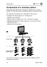
Page 12: ...The following components are required for the system Standard PC with Windows 7 Windows 8 Network card TCP IP Monitor with a resolution of 1024 768 pixel or higher OMEGA ACTIVE Access Point maximum te...

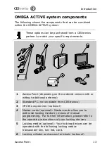
Page 13: ...rsion with or without additional antenna 2 Standard PC not available from CEStronics 3 CP100 programmer optional 4 Master cards optional Master cards allow you to authorize locking media by means of m...

Page 14: ...nt is supplied in two versions Access Point without additional antenna for RF ranges of up to 25 m Access Point with additional antenna for RF ranges of up to 40 m If you wish to retrofit Access Point...

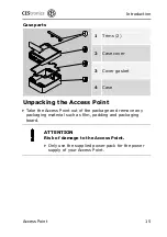
Page 15: ...ket 4 Case Unpacking the Access Point Take the Access Point out of the package and remove any packaging material such as film padding and packaging board ATTENTION Risk of damage to the Access Point O...

Page 16: ...plug in power supply 2 Socket for the network cable RJ45 3 LEDs for signalling RF traffic and server connection 4 Screw terminal for the relay contact 5 Screw terminal for the normally open relay cont...

Page 17: ...e RF ranges are observed Checking the range The maximum range for reading locking devices inside of buildings is 25 m without and 40 m with the additional antenna The RF range may vary significantly d...

Page 18: ...uality of the radio frequency RF link between the OMEGA server and your locking devices The RF TRACE MASTER triggers the following signals of your locking devices Flashing green LED strong RF link Fla...

Page 19: ...ll terminal The function is performed immediately If the green LED of your locking cylinder or wall terminal flashes the RF link is OK If the red LED of your locking cylinder or wall terminal flashes...

Page 20: ...ways easily accessible Make sure that all electrical connections can be separated at any time ATTENTION The Access Point may be damaged if not fitted properly Only skilled personnel may fit the Access...

Page 21: ...Access Point may not be fitted outdoors If the range for reading your locking devices is limited use the optional additional antenna See also Note on page 11 The Access Point is supplied preassembled...

Page 22: ...ts of the Access Point Do not disassemble the Access Point in rooms with built up static charge Ensure potential equalization when working on the Access Point to remove any static charge CAUTION Dange...

Page 23: ...Access Point Access Point 23 To gain access to the mounting holes the cover of the case must be removed Proceed as follows Push the two trims 1 on the right and the left hand side to the side with a...

Page 24: ...Point 24 Access Point Now the four fastening screws are 2 visible Release the four visible screws with a suitable Phillips tip screwdriver The screws cannot be screwed out completely but will be held...

Page 25: ...Fitting the Access Point Access Point 25 Lift the case cover away Now the four holes for mounting the Access Point are accessible...

Page 26: ...Point on the wall or ceiling see fitting drawing on page 36 Fasten the Access Point with four screws at the location selected When using fasteners observe the manufacturer s fitting instructions Only...

Page 27: ...ons Signal Meaning Green LED permanent Connection to server exists Green LED flashing Data communication with locking devices Red LED flashing No connection to server Green LED permanent Red LED flash...

Page 28: ...fastening screws Fold the two trims back into their covering position This completes the fitting of the Access Point Satisfy yourself that your locking devices are operating in RF mode Otherwise no c...

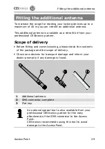
Page 29: ...Scope of delivery Before fitting and commissioning please check the contents of the package and the scope of delivery Check new devices for transport damage and inform your dealer promptly if any dama...

Page 30: ...on page 23 Remove the cover plug 1 at the Access Point if it exists 2 Remove the jumper 2 The jumper must be removed for the operation with the additional antenna The jumper 2 may only be set when the...

Page 31: ...of the jumper 2 while mounting the SMA connector Be careful not to damage any surrounding parts when attaching the SMA connector Finally refit the case cover as described on page 28 Screw the antenna...

Page 32: ...ter Verify the proper functioning of the plug in power supply of the Access Point with a suitable instrument multimeter ohmmeter Check the plug in power supply for mechanical damage Check the signaliz...

Page 33: ...ocking devices have no power Check the power supply of your locking devices Re establish the proper power supply of your locking devices For further information on establishing the power supply please...

Page 34: ...unctioning of the software as described in the OMEGA ACTIVE User Manual Verify the perfect functioning of your PC If you are not able to verify the perfect functioning please contact your PC dealer Yo...

Page 35: ...arts The Access Point does not require any spare parts for you to change If you need service please contact your professional CES partner Disposal Neither the Access Point nor any parts of the Access...

Page 36: ...Technical data 36 Access Point Technical data Version without additional antenna Version with additional antenna...

Page 37: ...nection Phonoplug 5 5 2 1 mm 5 5 mm 2 1 mm Relay contact Relay switching capacity 1 normally closed contact 1 normally open contact 5 A 250 V resistive load 5 A 250 V cos 0 3 5 A 30 V resistive load C...

Page 38: ...es two types of Master media the SYSTEM MASTER and the PROGRAM MASTER Optional transponder cards also have Master medium status CP100 programmer Device that allows you to program your locking devices...

Page 39: ...your have switched them into RF mode with the RF INI Master RF TRACE Master An optional Master card which enables you to test the quality of your RF link RF range The distance within which a safe tra...

Page 40: ...mage as a consequence of improper operation damage as a consequence of excess voltage damage as a consequence of fire water or smoke All technical data and features are subject to change without notic...

Page 41: ...1 204 229 info ces locks de CESitalia srl V d vecchie Fondamenta 4 Stra e d A Gr ndungen 4 I 39044 Egna Neumarkt BZ 39 0471 812 294 39 0471 812 294 info it ces eu www ces eu it CESrom srl Str Metalurg...

Reviews: