


SECTION 7
CESSNA
AIRPLANE AND SYSTEMS DESCRIPTION
MODEL 172S NAV III
VACUUM SYSTEM AND INSTRUMENTS
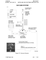
The vacuum system (refer to Figure 7-9) provides the vacuum
necessary to operate the standby attitude indicator. The system
consists of one engine-driven vacuum pump, a vacuum regulator,
the standby attitude indicator, a vacuum system air filter, and a
vacuum transducer. The GEA-71 Engine and Airframe unit receives
the signal from the vacuum transducer and shows vacuum on the
EIS ENGINE page. If vacuum available through the pump drops
below 3.5 in.hg., LOW VACUUM will appear in amber on the PFD.
ATTITUDE INDICATOR
The standby attitude indicator is a vacuum-powered gyroscopic
instrument, found on the center instrument panel below the MFD.
The Attitude Indicator includes a low-vacuum warning "flag"
("GYRO") that comes into view when the vacuum is below the level
necessary for reliable gyroscope operation.
VACUUM INDICATOR
The vacuum indicator is incorporated on the EIS ENGINE page,
found along the left side of the PFD during engine start or the left
edge of the MFD during normal operation. During reversionary
operation, the EIS bar appears along the left side of the operational
display.
LOW VACUUM ANNUNCIATION
A low vacuum condition is annunciated along the upper right side of
the PFD by a amber "LOW VACUUM" text box.
7-60 U.S.
172SPHAUS-03


