900 MHz & 2.4 GHz Manual
©
2020 Cervis, Inc
3
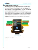
BU-xH1R Base Unit Features
•
Channel-Hopping DSSS Technology 900 MHz @ 10 mW, 2.4 GHz @ 100 mW
•
One Form C Relay
•
Up to Five Form A (SPST) Relay Outputs Standard Operation
•
Single Connector for Wiring Ease
•
Diagnostic LEDs
•
CAN bus Capable
•
Weatherproof Case
2.1
Base Unit Installation
Make sure the machine that the base unit will be attached to is disabled during
installation.
Use the configuration diagrams supplied by Cervis, Inc. to guide you in mounting the base unit
and connecting your wiring harness cables. Mounting of the base unit is left much to your
discretion with the following guidelines:
•
Before installing, make sure that the configuration diagrams supplied with the system are
available. Keep them where they are available at all times.
•
Make sure the wiring harness cable HN-1003 is at hand.
•
Always mount the base unit away from any intense radio or electric disturbance sources.
•
Make sure the mount is secure. Mount the unit where you have enough room for your
wiring harness connections.
•
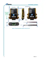
Mount so that the connectors are positioned down to avoid water pooling (see Figure 3).


