background image

900 MHz & 2.4 GHz Manual 

©

2020 Cervis, Inc 

2.2 

SmaRT BU-xH1R5 P1 Connector Wiring  


Figure 4. BU-xH1R5 P1 Connector Standard Wiring 


Table 1. SmaRT BU-xH1R5 P1 Connector Pin Assignments 

Pin  Name  Description 

  Pin  Name  Description 

K1 

Form A Relay 


K5 

Form A Relay 

L3 

Hi VAC Neutral/Hi 

–VDC 


K4 

Form A Relay 

L2 

Lo VAC Neutral/Lo 

–VDC 


K3 

Form A Relay 

L1 

+VDC or VAC Line 


10 

K2 

Form A Relay 

K6 

Form C Relay NC  


11 

KCOM 

Control Voltage  

K6 

Form C Relay Common 


12 

K6 

Form C Relay NO  


C

ab

le 

H

ar

n

ess

 H

N

-1003

 C

o

n

n

ecti

o

n

s


Summary of Contents for Wireless SmaRT BU- H1R Series

Page 1: ... 2020 Cervis Inc BU xH1R 900 MHz and 2 4 GHz Base Units Manual U099 0 2 ...

Page 2: ...icence exempt RSS standard s Operation is subject to the following two conditions 1 this device may not cause interference and 2 this device must accept any interference including interference that may cause undesired operation of the device Le présent appareil est conforme aux CNR d Industrie Canada applicables aux appareils radio exempts de licence Le fonctionnement est soumis aux deux condition...

Page 3: ...requency Energy 10 Appendix D Agency Identification Label Location 11 List of Figures Figure 1 SmaRT BU xH1R with SmaRT Handheld Remote Control Examples 1 Figure 2 BU xH1R LEDs 2 Figure 3 Mounting Holes and Cable Connector P1 4 Figure 4 BU xH1R5 P1 Connector Standard Wiring 5 Figure 5 BU xH1R3 P1 Connector CAN Wiring 6 Figure 6 HN 1003 Wiring Harness 10 Figure 7 Agency Identification Label Locatio...

Page 4: ...mote and remove power from the base unit before attempting any maintenance This will prevent accidental operation of the controlled machinery Remove power from the Base Unit by detaching the 12 pin cable from the base unit connector P1 or by removing the source power from the circuit Use a damp cloth to keep units clean Remove mud concrete dirt etc after use to prevent obstructing or clogging the ...

Page 5: ... base units can communicate with up to eight remotes on a first come first served basis Communication between a remote control and base unit is established at the factory using the Associate Procedure a process that can also be performed in the field The procedure seamlessly links the SmaRT handheld remote and the BU xH1R base unit without the need to open the enclosures of either unit Note Associ...

Page 6: ...h a SmaRT handheld unit without the need to open the case Using Channel Hopping Direct Sequence Spread Spectrum DSSS wireless technology at 900 MHz or 2 4 GHz the base unit provides a robust link with a SmaRT handheld remote in congested radio environments with an extensive line of sight communications range BU 9H1R3 and BU 2H1R3 CAN units provide a CAN bus interface for applications requiring wir...

Page 7: ...s Inc to guide you in mounting the base unit and connecting your wiring harness cables Mounting of the base unit is left much to your discretion with the following guidelines Before installing make sure that the configuration diagrams supplied with the system are available Keep them where they are available at all times Make sure the wiring harness cable HN 1003 is at hand Always mount the base un...

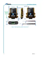
Page 8: ...igure 3 Mounting Holes and Cable Connector P1 BU xH1R BU xH1R 149 64 mm 5 89 102 mm 4 center to center 7 4mm 0 29 dia 118mm 4 7 133 mm 5 25 36mm 1 4 2 4 GHz 900 MHz 196 mm 7 7 146 05 mm 5 75 180 mm 7 08 Mount with Connectors Facing Downward ...

Page 9: ...nnector Pin Assignments Pin Name Description Pin Name Description 1 K1 Form A Relay 7 K5 Form A Relay 2 L3 Hi VAC Neutral Hi VDC 8 K4 Form A Relay 3 L2 Lo VAC Neutral Lo VDC 9 K3 Form A Relay 4 L1 VDC or VAC Line 10 K2 Form A Relay 5 K6 Form C Relay NC 11 KCOM Control Voltage 6 K6 Form C Relay Common 12 K6 Form C Relay NO Cable Harness HN 1003 Connections ...

Page 10: ...onnector Pin Assignments Pin Name Description Pin Name Description 1 K1 Form A Relay 7 CAMH CANH 2 L3 Hi VAC Neutral Hi VDC 8 K4 Form A Relay 3 L2 Lo VAC Neutral Lo VDC 9 CANL CANL 4 L1 VDC or VAC Line 10 K2 Form A Relay 5 K6 Form C Relay NC 11 KCOM Control Voltage 6 K6 Form C Relay Common 12 K6 Form C Relay NO Cable Harness HN 1003 Connections ...

Page 11: ...e base unit Out LED not active Check that the handheld LEDs are active when the appropriate buttons are pushed Health LED rapidly blinking Amber Indicates an internal problem Contact Cervis Inc service department Health LED blinking Red Over temperature indicated Check the outputs for loose wiring etc Active channel current consumption less than 1 A typical This is not a problem in cases where les...

Page 12: ...evice Enclosure Dimensions 119 mm x 133 mm x 36 mm 5 24 x 4 69 x 1 42 Durability High Impact Polymer Mounting Holes 7 4 mm 0 29 dia 102 mm center to center 4 center to center Indicators CAN RX TX Indicates CAN traffic Green Receive Red Transmit Out Green Output Active Health Green Pulse sec OK TX RX Indicates RF traffic Green Receive Red Transmit Power Yellow OK Red Grn Fault Outputs Relays One Fo...

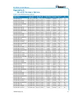
Page 13: ...R3 EXT LVA NOS CAN 900 MHz 10 mW 4 Form C 3 Form A 7 28 VAC External CAN No BU 9H1R5 EXT HVU 900 MHz 10 mW 6 Form C 5 Form A 100 240 VAC External NA Yes BU 9H1R3 EXT HVU CAN 900 MHz 10 mW 4 Form C 3 Form A 100 240 VAC External CAN Yes BU 9H1R5 EXT HVU NOS 900 MHz 10 mW 6 Form C 5 Form A 100 240 VAC External NA No BU 9H1R3 EXT HVU NOS CAN 900 MHz 10 mW 4 Form C 3 Form A 100 240 VAC External CAN No ...

Page 14: ...H1R3 EXT HVU NOS CAN 2 4 GHz 100 mW 4 Form C 3 Form A 100 240 VAC External CAN No Note BU xH1R CAN units are internally terminated at 4 3 k Termination can be removed at the factory Appendix B BU xH1R Wiring Harness Table 6 BU xH1R Wiring Harness Wiring Harness Part Number Cable P1 HN 1003 Figure 6 HN 1003 Wiring Harness Appendix C Exposure to Radio Frequency Energy SmaRT handheld remote units con...

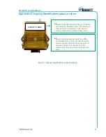
Page 15: ...D labels are located in the area shown The base unit label position is identical for both internal antenna and external antenna base units AGENCY LABEL Note Individual agency labels may differ but SmaRT base unit and handheld remote models use the illustrated label positions for all agency labels It is identical for both internal antenna and external antenna base units ...

Page 16: ...BU xH1R Base Unit Family U099 0 2 12 Visit our Web site at www cervisinc com 2020 Cervis Inc All rights reserved Content is subject to change without notice ...

Reviews: