


Warrior
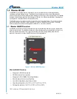
MU6E
U107.1.0
4
Table 1. MU6E Main PCB Diagnostic LEDs
LED
Name
LED State
Description
D1
+12V
Solid
Solid when OK
D2
+3.3V Logic
Solid
Solid when OK
D3
Master Health
Blinking
Unit OK, normal processor operation
D4
TX (Transmit)
Fast Blinking
Indicates RF Messages sent to handheld
D5
RX (Receive)
Fast Blinking
Indicates RF Messages received from handheld
D6
Slave Health
Blinking
Unit OK, normal processor operation
D7
Expansion TX
Fast Blinking
Indicates messages sent to expansion card
D8
Expansion RX
Fast Blinking
Indicates messages received from expansion
card
LED per
Relay (4)*
Relay State
Steady Lit
Relay Active
*Each relay has its own LED. The relay LED illuminates when commanded.
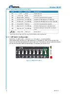
2.1.1 DIP Switch Configuration
Switch 8 on the DIP switch
— circled in
Green
— controls whether
transmitter/receiver association is UNLOCKED (1) or LOCKED (0). Most receivers ship from
Cervis, Inc. with the association DIP switch locked (0). This switch can be manually and virtually
unlocked to associate additional transmitters, if necessary (see Section 4.3).
Figure 3. MU6E DIP Switch
1
0
Summary of Contents for Warrior MU-6E-HVA
Page 1: ...2018 Cervis Inc MU6E Receiver Manual U107 1 0...
Page 6: ......