background image


PanelVisa


A-18 


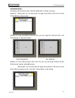
System menu 

Descriptions 

Password 

Update OS 

To receive new AP OS Ver. from COM Port. 

Yes*1 

Copy AP 

To Copy AP to another HMI from COM1/2. 

Yes*1 

Clear SRAM 

Clear battery backup data memory. 

Yes*1 

Run AP 

Press “Run AP” or “ENT” to communicate with P.L.C.. 

None*2 

Setting 

HMI keys and hardware functions testing. 

None 

LCD Test 

Check HMI LCD Display 

None 

Exit 

Press “ESC” to return HMI hardware self testing 

None 

*1.If  sets  a  BIOS  protection  password  to  HMI,  then  the  HMI  will  request  the  users  to 

enter BIOS password. 

*2. If sets a login user password in AP, when selects Run AP, it will request the user to 

enter BIOS password. 

Summary of Contents for GD058-TST

Page 1: ...PV Installation manual PanelVisa A 1 Industrial Touch Panel Touch Panel PanelVisa...

Page 2: ...vers of most PLCs invertors and temperature controllers on the market It is not only equipped with standard compact plastic case but also provides customized key types for users to design their favori...

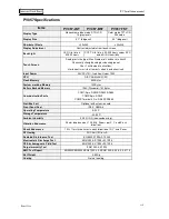
Page 3: ...1 9pin Female RS232 RS422 RS485 COM2 4pin Plug Connector RS422 RS485 Ethernet Port X Yes Extension Bus Port X X Front Panel Seal IP65 NEMA 4 Operating Temperature 0 50 C Storage Temperature 20 60 C Am...

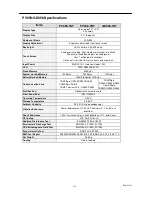
Page 4: ...nication Ports COM1 9pin Female RS232 RS422 RS485 COM2 4pin Plug Connector RS422 RS485 Ethernet Port X X Yes Extension Bus Port Profibus Options X X Front Panel Seal IP65 NEMA 4 Operating Temperature...

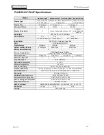
Page 5: ...RISC ARM 32Bit CPU Flash Memory 4M Bytes System working Memory 1M Bytes Battery Backed Memory 128K Standard 1M Bytes Communication Ports COM1 9pin RS232 RS422 RS485 COM2 9pin RS232 COM2 Terminal 4Pin...

Page 6: ...andard 1M Bytes Communication Ports COM1 9pin RS232 RS422 RS485 COM2 9pin RS232 COM2 Terminal 4Pin RS422 RS485 COM1 9pin RS232 RS422 RS485 Com2 25pin RS232 RS422 RS485 ProfiBus Port Optional with exte...

Page 7: ...rking Memory 512K Bytes 256K Bytes 512K Bytes Battery Backed Memory x x Communication Ports COM1 9pin Female RS232 COM2 4pin Terminal RS422 RS485 Real Time Clock X Optional X Optional X Optional X Opt...

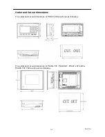
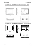
Page 8: ...A 8 Outlet and Cut out dimensions The outlet and cut out dimensions of PV037 LSK are shown as following The outlet and cut out dimensions of PL035 TST PL037LST PV037 LST LNT PV035 TST TNT are shown as...

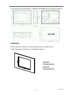
Page 9: ...al PanelVisa A 9 Industrial Touch Panel The outlet and cut out dimensions of PV057 LST BST TST PV058 TST TNT are shown as following The outlet and cut out dimensions of PL057 LST PL057 TST are shown a...

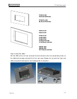
Page 10: ...nsions of GD057 LST GD058 TST are shown as following Installation Before setup HMI please cut a hole according to the cutout dimension Please see below pictures for your installation reference PL035 T...

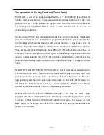
Page 11: ...the four assembling holes on the HMI with average strength form the rear side Please do not sew too tight and without equational strength or it will damage the touch panel PV037 LSK 159 5mmx88 5mm PV0...

Page 12: ...ESC and ENT again For double key s application users can operate to press together ESC and F1 F4 to act as a programmable function keys The Panel will automatically judge the data format or up down se...

Page 13: ...password is not set as a default situation With BIOS upgrade function wherever in the world whenever the HMI needs to be updated new functions this function supports upgrading without sending back to...

Page 14: ...ment program SW1 2 must set to Off ON ON To execute HMI application program SW5 Reserved ON Reserved OFF Reserved SW6 Reserved ON Reserved OFF Reserved 6 5 4 3 2 1 The PV037 PV057 has a BIOS password...

Page 15: ...th P L C normally When losing electricity during downloading or the PC breaks off downloading after restarting the HMI it will show Firmware Memory Checksum and Application Memory Checksum error It me...

Page 16: ...V037 LSK is shown as below Situation 1 When SW2 OFF it will show the default BIOS Ver B Situation 2 When SW2 ON it will show the Panel Setup screen or customized Version screen The startup menu of PV0...

Page 17: ...l the HMI has a beep sound Situation 2 It will enter BIOS mode and then you can adjust the startup mode is the Panel Setup or Run AP screen Panel Setup Mode Run AP Mode Situation 3 If the startup mode...

Page 18: ...AP Press Run AP or ENT to communicate with P L C None 2 Setting HMI keys and hardware functions testing None LCD Test Check HMI LCD Display None Exit Press ESC to return HMI hardware self testing None...

Page 19: ...ication components 2 The HMI will judge the data correctness during downloading AP When the PC sends AP data to HMI the HMI will show download AP screen and display related information automatically t...

Page 20: ...COM2 4 pin terminal RS422 and RS485 COM2 pin definitions Only PV057 PV058 series support is a DB 9P male Pin Function Pin Function 1 RS 485 6 RS 485 2 RS 232 RXD 7 RS 232 RTS 3 RS 232 TXD 8 RS 232 CTS...

Page 21: ...ance LED backlight and wide TFT LCD so adjusting the LCD brightness contrast are not necessary PV057 BST PV057 TST CCFL B L To adjust the PV057 LCD brightness Blue mode STN Color STN LCD TFT model can...

Page 22: ...l Peel the 24V wiring 1 25mm for 1 cm then plug in the power terminal Use line screw driver to screw the power terminal tight Package content We are appreciated for your purchasing our products Our st...

Page 23: ...less than 100 class3 Note that the ground cable must not be connected to the same ground point as the power circuit Installation Mount the HMI from the front of a suitable preserved hole Attached the...

Reviews: