Ceridian Dayforce Tuff Clock, User Manual
The Ceridian Dayforce Tuff Clock is a durable time tracking device perfect for any workplace. Ensure proper use by downloading the User Manual for free from manualshive.com. This manual provides step-by-step instructions on setting up and using the Tuff Clock efficiently, maximizing its benefits for your business.
Share
Download


Reviews:
No comments
Related manuals for Dayforce Tuff Clock
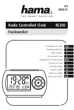
RC300
Brand: Hama Pages: 52
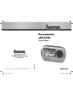
RC300
Brand: Hama Pages: 16

IAN 88977
Brand: Auriol Pages: 68

EX3000N
Brand: Amano Pages: 37

KH 2201
Brand: Kompernass Pages: 50

Idea 16573
Brand: Vimar Pages: 6

SixNix
Brand: Nixie Clock Pages: 31

98.1005
Brand: TFA Pages: 3

AR321S
Brand: Akai Pages: 5

AR250P
Brand: Akai Pages: 3

AR280P
Brand: Akai Pages: 17

BCR35DABRED
Brand: Bush Pages: 19

RCD215
Brand: RCA Pages: 3

RP 3755
Brand: RCA Pages: 8

Super Clock SC-5
Brand: Electronics International Pages: 16

616-1950
Brand: La Crosse Technology Pages: 4

617-1485W
Brand: La Crosse Technology Pages: 6

SAM Series
Brand: Sapling Pages: 72


