Section 10: Tail control rod & pitch control
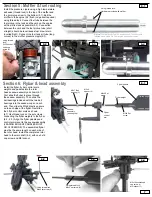
Use the radio to center the rudder servo. Mount the servo arm/horn perpendicular to
the tail pitch control rod threading the forward tail control rod ball link (found in the
upper frame bag) onto the pushrod (10.1). Adjust link at rear of tail system so that
the tail pitch slider is roughly centered on the tail output shaft (10.2). Connect the
ball links to the control balls at either end only when the rudder servo is centered
and the pitch slider is centered. Align the tail pushrod guides to help keep the
pushrod traveling without flex (10.3). Fix the favorable positions of the pushrod
guides (use CA glue) to avoid shifting/binding. Pushrod should travel through the
horizontal fin clamp on the right side (10.2 & 10.4).
10.1
10.2
10.3
Section 9: Tail boom supports & tail fin set
Attach the tail boom support struts to the base of the side frames using the
plastic spacer on the outside of the frame (9.1) . Attach the horizontal fin
(hardware found inside fin bag) and tail boom supports onto the horizontal
boom clamp (9.2 use the white plastic piece found with the canopy grommets
between the fin clamp and the fin). Screws are provided for mounting the verti-
cal fin in the package containing the fins (9.3).
9.1
9.2
9.4
Section 11: Throttle & Collective linkage
*Pushrod measurements include ball links from plastic end to plastic end.
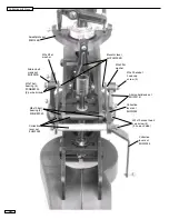
Before any pushrod adjustments are made center both sticks and all
servos on the transmitter. Attach the 103mm throttle control rod to the
throttle servo and the throttle arm on the carburetor. Be sure that when the
throttle collective stick is in the middle, that the throttle servo arm is straight
up, and that the carburetor barrel is half open and its control arm is also
pointed straight up. Adjust the collective control rod to 102mm for training
or to 100mm for 3D. Attach this rod to the collective control lever and col-
lective servo. Be sure the collective servo wheel is attached so that at mid
stick it is pointed straight up.
M3x8 Self tapping screw (2)
M3 washer (2)
9.3
M3 plastic spacer (2)
M3x16 socket head cap
screw (2)
M3 locknut (2)
M3x12 Self tapping
screw (2)
M3x20 socket head
cap screw (2)
M3 locknut (2)
9
Guides should be helping the pushrod
keep it’s shape when being flexed. All 3
guides may not have to be used.
10.4
Rudder pushrod should travel through
the tail boom clamp guide (this is the
way it is pre-assembled).
Collective pitch
servo
Throttle
servo
Rudder
servo


