background image

Page 48

Installation and Operation Manual - FW2900 

ENGLISH

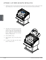
APPENDIx 6:  AIR TUBES AND BAFFLE INSTALLATION

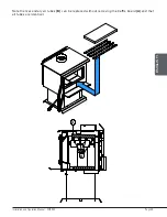
1.  Starting with the rear tube, lean and insert the right end of the secondary air tube into the rear 

right channel hole.  Then lift and insert the left end of the tube into the rear left channel.

2.  Align the notch in the left end of the tube 

with the key of the left air channel hole.  
Using a « Wise grip » hold the tube and 
lock it in place by turning the tube as 
shown.  Make sure the notch reaches 
the end of the key way.

3.  Put the baffle in place.

4.  Repeat steps 1 and 2 for the three other 

tubes.

5.  To remove the tubes use the above 

steps in reverse order.


Summary of Contents for CB00026

Page 1: ... FOLLOW THESE INSTRUCTIONS COULD RESULT IN PROPERTY DAMAGE BODILY INJURY OR EVEN DEATH READ AND KEEP THIS MANUAL FOR REFERENCE FW2900 CB00026 model MOBILE HOME Safety tested according to ULC S627 UL 1482 and UL 737 standards by an accredited laboratory ENGLISH US Environmental Protection Agency phase II certified wood stove compliant with 2020 cord wood standard Installation and Operation Manual 2...

Page 2: ......

Page 3: ...tove and the chimney that it is connected to It is also highly recommended to inform your home insurance company Please read this entire manual before installing and using this stove A primary alternative heat source should be available in the home This heating unit may serve as a supplementary heat source The manufacturer cannot be responsible for additional heating costs associated with the use ...

Page 4: ... Logs 14 3 5 Drying Time 15 4 Operating the Stove 16 5 1 The Use of a Fire Screen 16 5 2 Blower Operation 16 6 Burning Wood Efficiently 17 6 1 First Use 17 6 2 Lighting Fires 17 6 3 Combustion Cycles 18 6 4 Rekindling a Fire 19 6 5 Removing Ashes 19 6 6 Air Intake Control 20 6 7 Fire Types 20 7 Maintenance 22 7 1 Cleaning and Painting 22 7 2 Refractory Materials and Baffle 22 7 3 Glass Door 22 7 4...

Page 5: ...ation 39 10 5 Supply of Combustion Air 40 10 6 Installing the Chimney Connector 41 Appendix 1 Optional Fresh Air Intake Kit Installation 43 Appendix 2 Optional Fire Screen Installation 44 Appendix 3 Optional Blower Installation 45 Appendix 4 Optional Thermodisc Installation 46 Appendix 5 Log retainers installation 47 Appendix 6 Air Tubes and Baffle Installation 48 Appendix 7 Mobile Home Installati...

Page 6: ...Page 6 Installation and Operation Manual FW2900 ENGLISH CERTIFICATION PLATE ...

Page 7: ...ore opening the loading door NEVER USE GASOLINE LANTERN FUEL NAPHTHA FUEL OIL MOTOR OIL KEROSENE CHARCOAL LIGHTER FLUID OR SIMILAR LIQUIDS OR AEROSOLS TO START A FIRE IN THIS STOVE KEEP ALL SUCH LIQUIDS OR AEROSOLS WELL AWAY FROM THE STOVE WHILE IT IS IN USE Do not store fuel within heater minimum installation clearances Burn only seasoned natural firewood This appliance should always be maintaine...

Page 8: ...ting area and maximum burn time may vary subject to location in home chimney draft heat loss factors climate fuel type and other variables The recommended heated area for a given appliance is defined by the manufacturer as its capacity to maintain a minimum acceptable temperature in the designated area in case of a power failure 2 The maximum heat output dry cordwood is based on a loading density ...

Page 9: ... S627 10 North south ends of the logs visible East west sides of the logs visible 11 Mobile homes Canada or manufactured homes USA The US Department of Housing and Urban Development describes manufactured homes better known as mobile homes as follows buildings built on fixed wheels and those transported on temporary wheels axles and set on a permanent foundation In Canada a mobile home is a dwelli...

Page 10: ...mm 7 3 8 188mm 21 3 8 543mm 23 1 4 591mm 26 5 8 677mm 13 1 2 343mm 27 686mm O 6 153mm 9 1 4 235mm m 22 59mm 3 7 8 06mm 20 507mm 14 3 8 366mm 33 3 4 858mm 33 3 4 856mm 7 3 8 188mm 21 3 8 543mm 23 1 4 591mm 26 5 8 677mm 9 1 4 235mm 14 7 8 378mm 22 559mm 23 7 8 606mm 14 3 8 366mm 21 533mm 16 1 2 419mm 11 3 4 300mm 5 16 8mm 3 16 5mm 9 228mm 17 1 2 444mm 21 533mm 16 1 2 419mm 11 3 4 300mm 5 16 8mm 3 16...

Page 11: ...he back in an East West orientation Place a medium log about 3 x 3 on top of the biggest one Place another medium on coal bed on front of the biggest with another medium on top of it Place the last medium one in front If you need to stack the last piece over the ash lip make sure you always leave at least 1 5 8 inch between the last log and the inner wall of the combustion chamber There should be ...

Page 12: ...rature glass Ceramic glass cannot be recycled in the same way as normal glass so it should not be disposed of with regular household products Disposal at a waste management center is recommended 2 6 Zone Heating This stove is a space heater which means it is intended to heat the area it is installed in as well as spaces that connect to that area although to a lower temperature This is called zone ...

Page 13: ... in the correct moisture content range of 15 to 20 Refer to the following section for suggestions on preparing fuelwood and judging its moisture 3 Fuel Good firewood has been cut to the correct length for the stove split to a range of sizes and stacked outside to air dry until its moisture content is down to 15 to 20 DO NOT BURN GARBAGE LAWN CLIPPINGS OR YARD WASTE MATERIALS CONTAINING RUBBER INCL...

Page 14: ...they were fed large pieces of hardwood 3 2 Log Length Logs should be cut at least 1 25 mm shorter than the firebox so they fit in easily Pieces that are even slightly too long makes loading the stove very difficult The most common standard length of firewood is 16 400 mm 3 3 Log Size Firewood dries more quickly when it is split Large unsplit rounds can take years to dry enough to burn Even when dr...

Page 15: ...weather than in winter weather Split pieces dry more quickly than unsplit rounds Softwoods like pine spruce poplar and aspen take less time to dry than hardwoods They can be dry enough to burn after being stacked to air dry only for the summer months Hardwoods like oak maple and ash can take one or even two years to dry fully especially if the pieces are big Firewood dries more quickly when stacke...

Page 16: ...e screen is properly secured on the stove to avoid any risk of fire When the fire screen is in use it is important not to leave the stove unattended to respond promptly in the event of smoke spillage into the room Potential causes of smoke spillage are described in Section 10 The Venting System page 37 of this manual See Appendix 2 Optional Fire Screen Installation page 44 for installation instruc...

Page 17: ...r the first few times it may be wise to open doors and windows to ventilate the house Burn two or three small fires to begin the curing and conditioning process Then build bigger and hotter fires until there is no longer paint smell from the stove As hotter and hotter fires are burned more of the painted surfaces reach the curing temperature of the paint The smell of curing paint does not disappea...

Page 18: ...e fire is lit 6 2 3 Two Parallel Logs Method Two spit logs are placed in the firebox with a few sheets of twisted newspapers in between the logs Fine kindling is added across the two logs and some larger kindling across those log cabin style Newspaper is lit 6 2 4 Using Fire Starters Commercial fire starters can be used instead of a newspaper Some of these starters are made of sawdust and wax and ...

Page 19: ...nters the firebox This will ignite the new load quickly Secondly the charcoal will not be smothered by the new load of wood When the embers are simply spread inside the combustion chamber the new load smoulder for a long time before igniting Close the air control only when the firebox is full of bright turbulent flames the wood is charred and its edges are glowing The heater should not be left una...

Page 20: ...e other hand too much air can make the fire uncontrollable creating very high temperatures in the unit as well as in the chimney and seriously damaging them A reddish glow on the unit and on the chimney components indicates overheating Excessive temperatures can cause a chimney fire 6 7 Fire Types Using the air intake control is not the only way to match the appliance heat output to the desired te...

Page 21: ...o a coal bed of the same size The flaming phase of the fire lasts for roughly the first half of the burn cycle and the second half is the coal bed phase during which there is little or no flame The burning time expected from this stove including both phases will vary depending on a number of things such as firebox size the amount of wood loaded the species of the wood the wood moisture content the...

Page 22: ...panels baffle and air tubes will wear over time Defective parts should always be replaced with original parts To avoid premature deterioration follow the lighting and reloading procedures in section 6 Burning Wood Efficiently and also avoid letting the heater run with the air intake fully open for entire burn cycles 7 1 Cleaning and Painting Painted and plated surfaces can be wiped down with a sof...

Page 23: ...wn streaks are coming from the edge of the glass it is time to replace the gasket around the glass The glass gasket should be self adhesive Always replace the gasket with a genuine one 7 3 2 Replacement The glass used is a ceramic glass 5 32 4 mm thick tested to reach temperatures up to 1400ºF If the glass breaks it must be replaced with one having the same specification To remove or replace the g...

Page 24: ... best efficiency the door must provide a perfect seal with the firebox The tightness of the door seal can be verified by closing and latching the door on a strip of paper The test must be performed all around the door If the paper slips out easily anywhere replace the gasket 7 4 1 Gasket It is important to replace the gasket with another having the same diameter and density to maintain a good seal...

Page 25: ...latively cooler chimney flue of a slow burning fire As a result creosote residue accumulates on the flue lining When ignited this creosote makes an extremely hot fire The chimney connector and chimney should be inspected at least once every two months during the heating season to determine if a creosote buildup has occurred If a significant layer of creosote has accumulated 3 mm or more it should ...

Page 26: ...leaning process some will choose to do it themselves The chimney should be checked regularly for creosote build up Inspection and cleaning of the chimney can be facilitated by removing the baffle See Appendix 6 Air Tubes and Baffle Installation for more details 7 5 3 Chimney Fire Regular chimney maintenance and inspection can prevent chimney fires If you have a chimney fire follow these steps 1 Cl...

Page 27: ... of combustion air shall be provided to the room 8 1 Mobile Home May be installed in a mobile home The installation requires a fresh air kit sold separately WARNING DO NOT INSTALL IN THE SLEEPING ROOM THE STOVE MUST BE ATTACHED TO THE STRUCTURE OF THE MOBILE HOME CAUTION THE STRUCTURAL INTEGRITY OF THE MOBILE HOME FLOOR WALL CEILING AND ROOF MUST BE MAINTAINED 8 2 Regulations Covering Stove Instal...

Page 28: ...es shown in this section have been determined by tests according to procedures set out in safety standards ULC S627 Canada UL 1482 U S A and UL 737 U S A When the stove is installed so that its surfaces are at or beyond the minimum clearances specified combustible surfaces will not overheat under normal and even abnormal operating conditions No part of the stove or flue pipe may be located closer ...

Page 29: ...Page 29 Installation and Operation Manual FW2900 ENGLISH A B E D CAN 48 122 cm US 36 92 cm F F C Clearances Back and side Clearances Corner 84 L 2133 mm Ve Ho N Clearances Ceiling ...

Page 30: ...4 mm 31 1 4 794 mm F 21 552 mm 21 552 mm F 21 1 2 546 mm 21 1 2 546 mm 9 1 1 With Heat Shield AC0276214 APPLIANCE CLEARANCES WITH DOUBLE WALL PIPE CONNECTOR DISTANCES13 FROM DOUBLE WALL PIPE CONNECTOR Canada USA Canada USA A 3 76 mm 3 76 mm D 6 1 4 159 mm 6 1 4 159 mm B 4 102 mm 4 102 mm E 13 1 4 337 mm 13 1 4 337 mm C 3 76 mm 3 76 mm F 12 1 2 318 mm 12 1 2 318 mm 13 The pipe distances listed in t...

Page 31: ...819 mm 32 819 mm F 21 552 mm 21 552 mm F 21 549 mm 21 549 mm 9 1 3 With Heat Shield AC02710 and Lowered Ceiling16 APPLIANCE CLEARANCES WITH DOUBLE WALL PIPE CONNECTOR DISTANCES FROM PIPE CONNECTOR WITH DOUBLE WALL PIPE CONNECTOR Canada USA Canada USA A 5 127 mm 5 127 mm D 8 1 4 210 mm 8 1 4 210 mm B 6 152 mm 6 152 mm E 15 1 4 387 mm 15 1 4 387 mm C 5 127 mm 5 127 mm F 14 1 2 368 mm 14 1 2 368 mm L...

Page 32: ...ECTOR Canada USA Canada USA A 11 279 mm 11 279 mm D 14 1 4 362 mm 14 1 4 362 mm B 24 610 mm 24 610 mm E 33 1 4 845 mm 33 1 4 845 mm C 13 330 mm 13 330 mm F 22 1 2 572 mm 22 1 2 572 mm 9 1 6 Mobile Home With Heat Shield AC02762 It is strictly forbidden to install a unit with a single wall pipe in a mobile home APPLIANCE CLEARANCES WITH DOUBLE WALL PIPE CONNECTOR DISTANCES17 FROM PIPE CONNECTOR WITH...

Page 33: ...natives No protection is required if the unit is installed on a non combustible floor ex concrete FLOOR PROTECTION Canada USA G18 8 203 mm N A H 8 203 mm N A I 18 457 mm From door opening 16 203 mm From door opening J N A 8 203 mm H I G J Floor Protection 9 3 Reducing Clearances Safely It is often desired to use as little space as possible when installing a wood stove To do this it is possible to ...

Page 34: ... non combustible board spaced out at least 1 25 mm by non combustible spacers 50 18 457 mm 33 24 610 mm Ceramic tiles or equivalent non combustible material on non combustible board with a minimum of 24 gauge 0 61 mm sheet metal backing spaced out at least 1 25 mm by non combustible spacers 67 12 305 mm 50 24 610 mm Brick spaced out at least 1 25 mm by non combustible spacers 50 18 457 mm N A N A ...

Page 35: ...ction to match each letter to a clearance A Minimum clearance between the appliance top and an unshielded combustible ceiling 49 1245 mm B Shield extension above the appliance 20 500 mm C Minimum space behind the shield 1 25 mm In Canada 21 mm D Clearance along the bottom of the shield minimum 1 25 mm and maximum 3 75 mm E Minimum clearance along the top of the shield at the ceiling 3 75 mm F Moun...

Page 36: ...Page 36 Installation and Operation Manual FW2900 ENGLISH Heat shield clearances Heat shield clearances Heat shield clearances ...

Page 37: ...ameter of at least 5 Canada only or no more than 7 is permitted if it allows the proper venting of combustion gases and that such application is verified and authorized by a qualified installer Otherwise the diameter of the flue should be 6 To be suitable a factory built metal chimney must comply with UL 103 HT U S A or ULC S629 Canada 10 2 1 Factory Built Metal Chimneys These are sometimes referr...

Page 38: ...lashing must be installed and sealed with silicone adhesive 10 2 3 Masonry Chimneys The stove may also be connected to a masonry chimney provided the chimney complies with the construction rules found in the building code enforced locally The chimney must have either a clay liner or a suitably listed stainless steel liner If the masonry chimney has a square or rectangular liner that is larger in c...

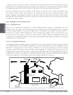
Page 39: ...y should be installed up through the heated space of the house not out and up an outside wall Second the chimney should penetrate to the top of the building at or near the highest heated space Venting systems that rise straight up from the stove flue collar provide the best performance Chimneys that rise inside the warm space of the house tend to provide a small amount of draft even when there is ...

Page 40: ...from the basement from a garage or any enclosed space Air must be drawn from a ventilated crawl space under the floor or directly from outside Install a flexible or rigid insulated pipe HVAC type must comply to ULC S110 and or UL 181 Class 0 or Class 1 to the fresh air intake Where a mobile home has been converted to a standard house by mounting it on a permanent basement foundation the supply of ...

Page 41: ... compliant Therefore a list of rules found in solid fuel installation codes apply to the installation of a single wall pipe Double wall chimney connectors are tested and certified The rules for double wall pipe are found in the manufacturer s installation instructions These rules will be very different than those for single wall 10 6 1 Installation of Single Wall Chimney Connector The chimney conn...

Page 42: ...bly must make allowance for expansion elbows in assemblies allow for expansion straight assemblies should include an inspection wrap with one end unfastened or a telescopic section Minimum upward slope towards the chimney in ft 20 mm m One end of the assembly must be securely fastened to the flue collar with 3 sheet metal screws and the other end securely fastened to the chimney There must be prov...

Page 43: ...on of a fresh air intake kit A and an insulated fresh air intake pipe HVAC type must meet ULC S110 or UL 181 class 0 or class 1 B sold separately Refer to air intake kit installation instructions for more details The configutation of this appliance do not allow the air intake to be installed underneath the pedestal It can only be installed on the back A B DETAIL F F ...

Page 44: ...PA 1 Open the door 2 Hold the fire screen by the two handles and bring it close to the door opening 3 Lean the upper part of the fire screen against the top door opening making sure to stove the top fire screen brackets behind the primary air deflector 4 Lift the fire screen upwards and push the bottom part towards the stove then let the fire screen rest on the bottom of the door opening Warning N...

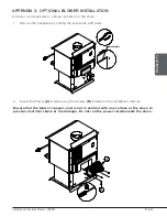
Page 45: ... the stove 1 Remove the backplate by cutting the knockouts with pliers MICROJOINTS 2 Screw the blower A in place using the screws B included in the installation manual Ensure that the blower s power cord is not in contact with any surface of the stove to prevent electrical shock or fire damage Do not run the power cord beneath the stove B A ...

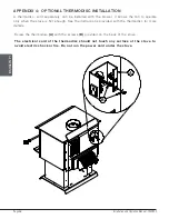
Page 46: ... It allows the fan to operate only when the stove is hot enough See the instructions provided with the thermodisc for more details Screw the thermodisc A with the screws B provided on the back of the stove The electrical cord of the thermodisc should not touch any surface of the stove to avoid electric shock or fire Do not run the power cord under the stove A B ...

Page 47: ...Page 47 Installation and Operation Manual FW2900 ENGLISH Appendix 5 LOG RETAINERS INSTALLATION 1 2 3 ...

Page 48: ...en lift and insert the left end of the tube into the rear left channel 2 Align the notch in the left end of the tube with the key of the left air channel hole Using a Wise grip hold the tube and lock it in place by turning the tube as shown Make sure the notch reaches the end of the key way 3 Put the baffle in place 4 Repeat steps 1 and 2 for the three other tubes 5 To remove the tubes use the abo...

Page 49: ...Page 49 Installation and Operation Manual FW2900 ENGLISH Note that secondary air tubes B can be replaced without removing the baffle board A and that all tubes are identical B A ...

Page 50: ...Page 50 Installation and Operation Manual FW2900 ENGLISH Appendix 7 MOBILE HOME INSTALLATION ...

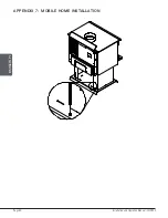
Page 51: ... the metal plate C and the refractory brick A 2 Unscrew the two metal rounds using an adjustable wrench 3 Using a hammer remove the third metal rounds 4 Place the ash pan support A in the bottom of the base of the stove 5 Place the refractory brick A the ash plug B and the ash pan C 6 Screw the metal plate A behind the stove A B C A A B C A A B C A B DETAIL F F ...

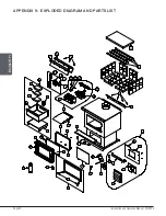
Page 52: ...ISH Appendix 9 EXPLODED DIAGRAM AND PARTS LIST 5 1 7 8 9 48 16 21 22 24 25 23 26 33 13 12 11 18 19 19 19 18 19 19 19 20 18 19 19 19 18 19 19 19 20 19 19 20 10 45 2 3 4 6 14 15 27 28 29 30 31 32 34 35 36 37 38 39 36 40 41 42 43 44 47 46 49 16 50 16 51 17 6 ...

Page 53: ...EFLECTOR 1 10 SE65305 AIR CONTROL DAMPER ASS 1 11 30187 STAINLESS WASHER ID 17 64 X OD 1 2 1 12 30206 ZINC WASHER 5 16 ID X 3 4 OD 1 13 30506 SCREW PAN TORX TYPE F 1 4 20 X 1 BLACK 1 14 SE46221 CENTURY 2 3 INSTRUCTION MANUAL KIT 1 15 PL74063 AIR DEFLECTOR 1 16 30154 BLACK SCREW 10 X 5 8 QUADREX 2 TYPE A 10 17 49028 5 WHITE AIR INTAKE TERMINATION 1 18 29007 3 1 4 X 9 X 1 1 4 REFRACTORY BRICK 4 19 2...

Page 54: ...09909 02 BLOWER HOUSING 1 39 44073 CROSSFLOW BLOWER 115V 60Hz 39W 100 CFM 1 40 44080 RHEOSTAT WITHOUT NUT MODEL KBMS 13BV 1 41 44087 RHEOSTAT NUT 1 42 44085 RHEOSTAT KNOB 1 43 PL74047 PEDESTAL FRONT COVER 1 44 AC07869 3 8 BLACK COIL HANDLE 1 45 AC05959 METALLIC BLACK STOVE PAINT 342 g 12oz AEROSOL 1 46 AC01315 RIGID FIRESCREEN 1 47 30898 ROUND WOODEN BLACK HANDLE 2 48 AC02081 5 Ø FRESH AIR INTAKE ...

Page 55: ...y part or unit after inspection and investigation of the defect The manufacturer may at its discretion fully discharge all obligations with respect to this warranty by refunding the wholesale price of any warranted but defective parts The manufacturer shall in no event be responsible for any uncommon indirect consequential damages of any nature which are in excess of the original purchase price of...

Page 56: ...this document from time to time and cannot be responsible for problems injuries or damages arising out of the use of information contained in any document obtained from unauthorized sources Stove Builder International inc 250 rue de Copenhague St Augustin de Desmaures Québec Canada G3A 2H3 418 908 8002 https www century heating com en tech sbi international com ...

Reviews: